GE Multilin T35 Transformer Protection System 9-11
9 COMMISSIONING 9.2 DIFFERENTIAL CHARACTERISTIC TEST EXAMPLES
9
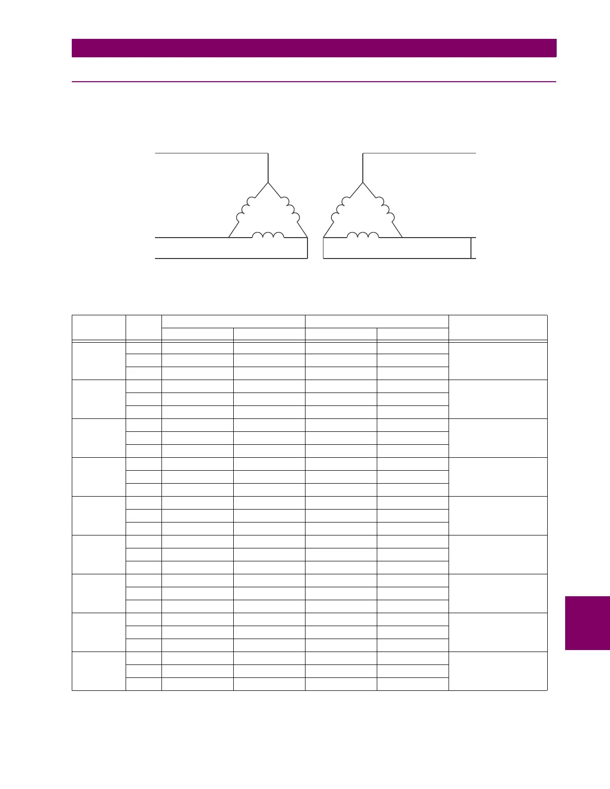
9.2.5 TEST EXAMPLE 4
D/D0° TRANSFORMER WITH PHASE B TO C FAULT ON THE SECONDARY DELTA WINDING.
Transformer: D/D0°, 20 MVA, 115/12.47 kv, CT1 (200:1), CT2 (1000:1)
Figure 9–5: CURRENT DISTRIBUTION OF D/D TRANSFORMER WITH AN a TO b FAULT ON THE LV SIDE
TEST PHASE INJECTED CURRENT DISPLAYED CURRENT STATUS
W1 CURRENT W2 CURRENT DIFFERENTIAL RESTRAINT
Balanced
Condition
A0 ∠0° 0 ∠0° 0 ∠0° 0 ∠0° Not Applicable
B 0.435 ∠–90° 0.8 ∠–270° 0 ∠0° 0.8 ∠–270°
C 0.435 ∠–270° 0.8 ∠–90° 0 ∠0° 0.8 ∠–90°
Min Pickup A 0 ∠0° 0 ∠0° 0 ∠0° 0 ∠0° Block
I
d
= 0.065 < Min PKP
B 0.09 ∠–90° 0.23 ∠–270° 0.065 ∠0° 0.230 ∠–270°
C 0.09 ∠–270° 0.23 ∠–90° 0.065 ∠0° 0.230 ∠–90°
Min Pickup A 0 ∠0° 0 ∠0° 0 ∠0° 0 ∠0° Operate
I
d
= 0.101 > Min PKP
B 0.21 ∠–90° 0.486 ∠–270° 0.102 ∠0° 0.486 ∠–270°
C 0.21 ∠–270° 0.486 ∠–90° 0.101 ∠0° 0.486 ∠–90°
Slope 1 A 0 ∠0° 0 ∠0° 0 ∠0° 0 ∠0° Block
I
d
/I
r
= 14% < 15%
B 0.651 ∠–90° 1.39 ∠–270° 0.195 ∠0° 1.39 ∠–270°
C 0.651 ∠–270° 1.39 ∠–90° 0.195 ∠0° 1.39 ∠–90°
Slope 1 A 0 ∠0° 0 ∠0° 0 ∠0° 0 ∠0° Operate
I
d
/I
r
= 16.8% > 15%
B 0.63 ∠–90° 1.39 ∠–270° 0.233 ∠0° 1.39 ∠–270°
C 0.63 ∠–270° 1.39 ∠–90° 0.233 ∠0° 1.39 ∠–90°
Intermediate
Slope 1 & 2
A0 ∠0° 0 ∠0° 0 ∠0° 0 ∠0° Block
I
d
/I
r
= 52.6%
< 60%
computed
B1.2 ∠–90° 4.63 ∠–270° 2.44 ∠–270° 4.63 ∠–270°
C1.2 ∠–270° 4.63 ∠–90° 2.44 ∠–90° 4.63 ∠–90°
Intermediate
Slope 1 & 2
A0 ∠0° 0 ∠0° 0 ∠0° 0 ∠0° Operate
I
d
/I
r
= 68.8%
> 60%
computed
B0.8 ∠–90° 4.63 ∠–270° 3.18 ∠–270° 4.63 ∠–270°
C0.8 ∠–270° 4.63 ∠–90° 3.18 ∠–90° 4.63 ∠–90°
Slope 2 A 0 ∠0° 0 ∠0° 0 ∠0° 0 ∠0° Block
I
d
/I
r
= 93.2%
< Slope 2 = 95%
B 0.315 ∠–90° 8.33 ∠–270° 7.77 ∠–270° 8.33 ∠–270°
C 0.315 ∠–270° 8.33 ∠–90° 7.77 ∠–90° 8.33 ∠–90°
Slope 2 A 0 ∠0° 0 ∠0° 0 ∠0° 0 ∠0° Operate
I
d
/I
r
= 96%
> Slope 2 = 95%
B 0.18 ∠–90° 8.33 ∠–270° 8 ∠–270° 8.33 ∠–270°
C 0.18 ∠–270° 8.33 ∠–90° 8 ∠–90° 8.33 ∠–90°
828739A1.CDR
D/d0° Transformer
F
I (f) = 0
A
I (f) = 0.866 pu –90°
b
∠
I (f) = 0
a
I (f) = 0.866 pu –270°
c
∠
I (f) = 0.866 pu –90°
B
∠
I (f) = 0.866 pu –270°.
C
∠
A
B
C
A
B
C
H winding X winding

 Loading...


