GE Multilin T35 Transformer Protection System 2-15
2 PRODUCT DESCRIPTION 2.2 SPECIFICATIONS
2
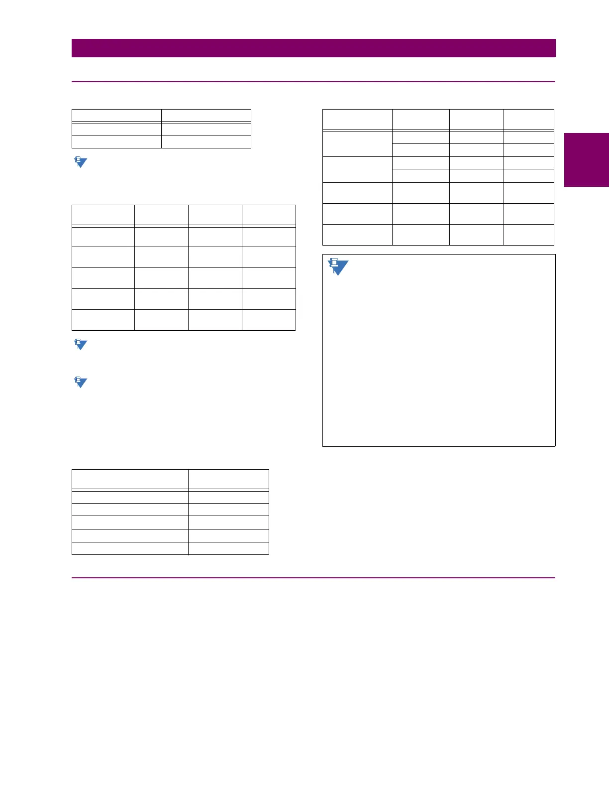
2.2.9 INTER-RELAY COMMUNICATIONS
SHIELDED TWISTED-PAIR INTERFACE OPTIONS
RS422 distance is based on transmitter power and
does not take into consideration the clock source
provided by the user.
LINK POWER BUDGET
These power budgets are calculated from the manu-
facturer’s worst-case transmitter power and worst
case receiver sensitivity.
The power budgets for the 1300 nm ELED are calcu-
lated from the manufacturer's transmitter power and
receiver sensitivity at ambient temperature. At
extreme temperatures these values deviate based
on component tolerance. On average, the output
power decreases as the temperature is increased by
a factor 1dB / 5°C.
MAXIMUM OPTICAL INPUT POWER
TYPICAL LINK DISTANCE
Compensated difference in transmitting and receiving (channel
asymmetry) channel delays using GPS satellite clock: 10 ms
2.2.10 ENVIRONMENTAL
AMBIENT TEMPERATURES
Storage temperature: –40 to 85°C
Operating temperature: –40 to 60°C; the LCD contrast can be
impaired at temperatures less than –
20°C
HUMIDITY
Humidity: operating up to 95% (non-condensing) at
55°C (as per IEC60068-2-30 variant 1, 6
days).
OTHER
Altitude: 2000 m (maximum)
Pollution degree: II
Overvoltage category: II
Ingress protection: IP20 front, IP10 back
Noise: 0 dB
INTERFACE TYPE TYPICAL DISTANCE
RS422 1200 m
G.703 100 m
EMITTER,
FIBER TYPE
TRANSMIT
POWER
RECEIVED
SENSITIVITY
POWER
BUDGET
820 nm LED,
Multimode
–20 dBm –30 dBm 10 dB
1300 nm LED,
Multimode
–21 dBm –30 dBm 9 dB
1300 nm ELED,
Singlemode
–23 dBm –32 dBm 9 dB
1300 nm Laser,
Singlemode
–1 dBm –30 dBm 29 dB
1550 nm Laser,
Singlemode
+5 dBm –30 dBm 35 dB
EMITTER, FIBER TYPE MAX. OPTICAL
INPUT POWER
820 nm LED, Multimode –7.6 dBm
1300 nm LED, Multimode –11 dBm
1300 nm ELED, Singlemode –14 dBm
1300 nm Laser, Singlemode –14 dBm
1550 nm Laser, Singlemode –14 dBm
EMITTER TYPE CABLE
TYPE
CONNECTOR
TYPE
TYPICAL
DISTANCE
820 nm LED,
multimode
62.5/125 μmST 1.65 km
50/125 μmST1.65 km
1300 nm LED,
multimode
62.5/125 μmST 4 km
50/125 μmST 4 km
1300 nm ELED,
single mode
9/125 μm ST 11.4 km
1300 nm Laser,
single mode
9/125 μm ST 64 km
1550 nm Laser,
single-mode
9/125 μm ST 105 km
Typical distances listed are based on the follow-
ing assumptions for system loss. As actual losses
vary from one installation to another, the distance
covered by your system may vary.
CONNECTOR LOSSES (TOTAL OF BOTH ENDS)
ST connector 2 dB
FIBER LOSSES
820 nm multimode 3 dB/km
1300 nm multimode 1 dB/km
1300 nm singlemode 0.35 dB/km
1550 nm singlemode 0.25 dB/km
Splice losses: One splice every 2 km,
at 0.05 dB loss per splice.
SYSTEM MARGIN
3 dB additional loss added to calculations to compensate for
all other losses.

 Loading...


