GE Multilin T35 Transformer Protection System 3-29
3 HARDWARE 3.3 DIRECT INPUT/OUTPUT COMMUNICATIONS
3
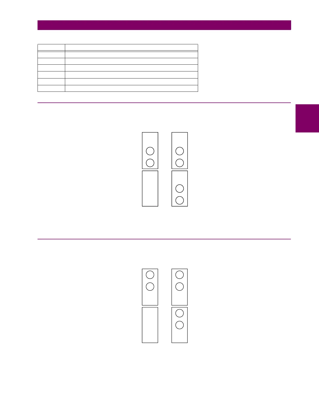
3.3.2 FIBER: LED AND ELED TRANSMITTERS
The following figure shows the configuration for the 7A, 7B, 7C, 7H, 7I, and 7J fiber-only modules.
Figure 3–29: LED AND ELED FIBER MODULES
3.3.3 FIBER-LASER TRANSMITTERS
The following figure shows the configuration for the 72, 73, 7D, and 7K fiber-laser module.
Figure 3–30: LASER FIBER MODULES
7Q Channel 1: G.703, channel 2: 1300 nm, single-mode, laser
7R G.703, 1 channel
7S G.703, 2 channels
7T RS422, 1 channel
7V RS422, 2 channels, 2 clock inputs
7W RS422, 2 channels
Table 3–3: CHANNEL COMMUNICATION OPTIONS (Sheet 2 of 2)
MODULE SPECIFICATION
7A, 7B, and
7C modules
7H, 7I, and
7J modules
1 channel 2 channels
Rx1
Rx1
Rx2
Tx1 Tx1
Tx2
831719A3.CDR
1 channel 2 channels
Rx1 Rx1
Rx2
Tx1 Tx1
Tx2
831720A5.CDR
72 and 7D
modules
73 and 7K
modules

 Loading...


