3-36 T35 Transformer Protection System GE Multilin
3.3 DIRECT INPUT/OUTPUT COMMUNICATIONS 3 HARDWARE
3
To recover the Rx clock from the data-stream, an integrated DPLL (digital phase lock loop) circuit is utilized. The DPLL is
driven by an internal clock, which is 16-times over-sampled, and uses this clock along with the data-stream to generate a
data clock that can be used as the SCC (serial communication controller) receive clock.
3.3.6 RS422 AND FIBER INTERFACE
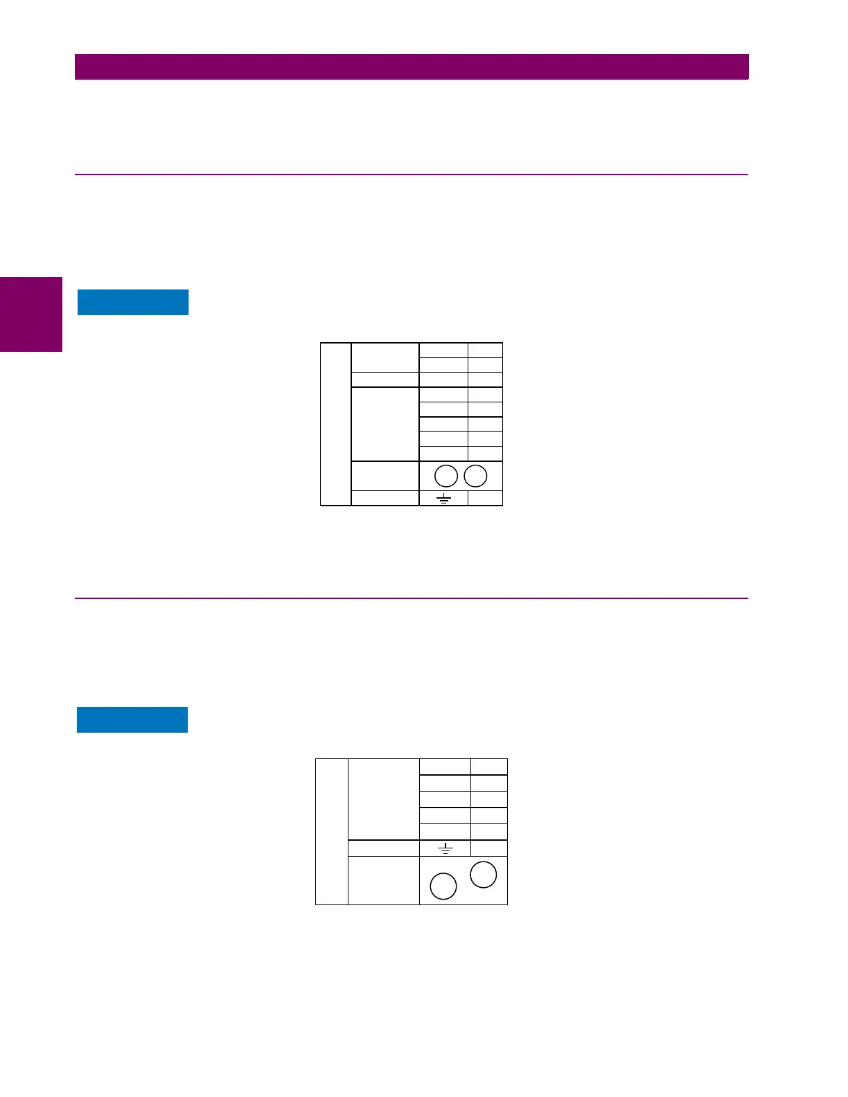
The following figure shows the combined RS422 plus fiberoptic interface configuration at 64K baud. The 7L, 7M, 7N, 7P,
and 74 modules are used in two-terminal with a redundant channel or three-terminal configurations where channel 1 is
employed via the RS422 interface (possibly with a multiplexer) and channel 2 via direct fiber.
AWG 20-24 twisted shielded pair is recommended for external RS422 connections and ground the shield only at one end.
For the direct fiber channel, address power budget issues properly.
When using a LASER Interface, attenuators can be necessary to ensure that you do not exceed
maximum optical input power to the receiver.
Figure 3–40: RS422 AND FIBER INTERFACE CONNECTION
Connections shown above are for multiplexers configured as DCE (data communications equipment) units.
3.3.7 G.703 AND FIBER INTERFACE
The figure below shows the combined G.703 plus fiberoptic interface configuration at 64 kbps. The 7E, 7F, 7G, 7Q, and 75
modules are used in configurations where channel 1 is employed via the G.703 interface (possibly with a multiplexer) and
channel 2 via direct fiber. AWG 24 twisted shielded pair is recommended for external G.703 connections connecting the
shield to pin 1a at one end only. For the direct fiber channel, address power budget issues properly. See previous sections
for additional details on the G.703 and fiber interfaces.
When using a laser Interface, attenuators can be necessary to ensure that you do not exceed the
maximum optical input power to the receiver.
Figure 3–41: G.703 AND FIBER INTERFACE CONNECTION
Tx2
Rx2
842777A2.CDR
~8a
7L, 7M, 7N,
7P, and 74
Shield
Tx –
Rx –
Tx +
Rx +
RS422
communications
~4b
~3a
~3b
~6a
~2a
RS422
channel 1
Surge
+
–
~7a
~8b
Clock
channel 1
Common
~2b
COM
Fiber
channel 2
Rx2
Tx2
842778A2.CDR
~3b
75, 7E, 7F, 7G,
and 7Q
Rx +
Shield
Tx –
Rx –
Tx +
G.703
communications
~2b
~1b
~1a
~3a
~2a
G.703
channel 1
Surge
Fiber
channel 2

 Loading...


