ADV200 SP • Quick start up guide - Specification and installation 39
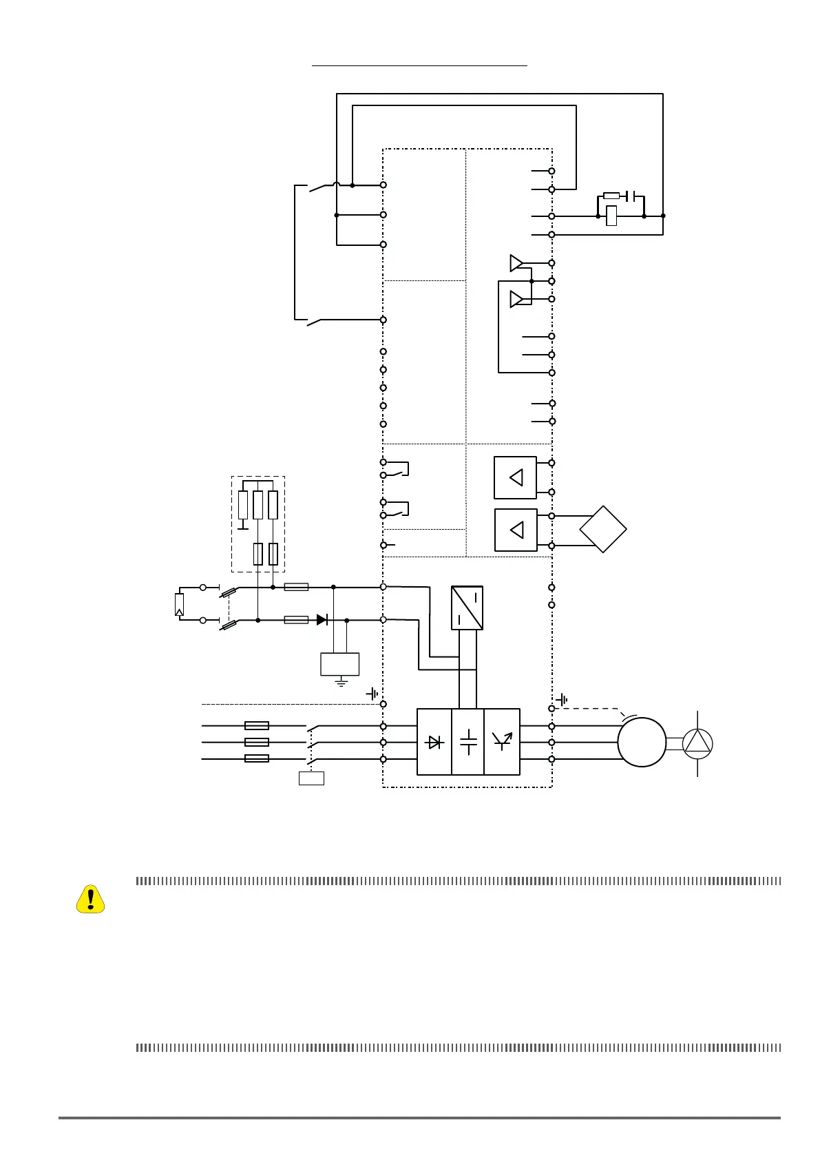
Figure 5.5.4: PV power supply and AC mains power supply
+ 24V
L1
K1M
5
L1
L2
L3
PE
0 V24
1
2
3
4
6
SMPS
COM ID
S3
C3
C2
12
7
Digital input E mon
(Enable)
R11
R14
R21
R24
RS 485
S1+
S1-
C1
+ 10 V
- 10 V
0 V 10
1
2
Analog input 1Analog input 2
-
4
3
-
+
+
L2
L3
U
V
W
Multi ref sel 0 src
FR forward src
5
C1
6
13
IC1
COM Dig. Out.3/4
Dig. Out.3
M
3~
8
9
10
11
Dig. Output 2
(Relay 2)
Multi ref sel 1 src
IS1
14
PS Dig. Out.3/4
Dig. Out.4
BR1
BR2
Dig. Output 1
(Relay 1)
Drive OK
Drive ready
F1
K1M
K2
Sistema di pompaggio
Analog
output 1
Analog
output 2
IS2
IC2
+ 24 V
0 V
External
Power
Supply
K3
F2
Insulator
control
C
D
Radiation
Sensor
PV Panel
SPD
+
-
(2)
(2) PAR 1314 Digital output 3 src = PAD15
These protection devices must have a rated voltage greater than or equal to the no-load voltage of the string
output.
rating that does not exceed the manufacturer’s recommendations for panel protection.
two fuses, one at each pole.
Caution
 Loading...


