—————— Instruction manual ——————
495
A2.5.2 Connection between TPD32-EV-CU and TPD32-EV-FC units via external I/O
InFWversion11.00andhigherfortheTPD32-EV/TPD32-EV-CU,youcancontrolaTPD32-EV-FCunitvia
externalinputsandoutputs(I/O)(withoutneedingaberopticsconnection).
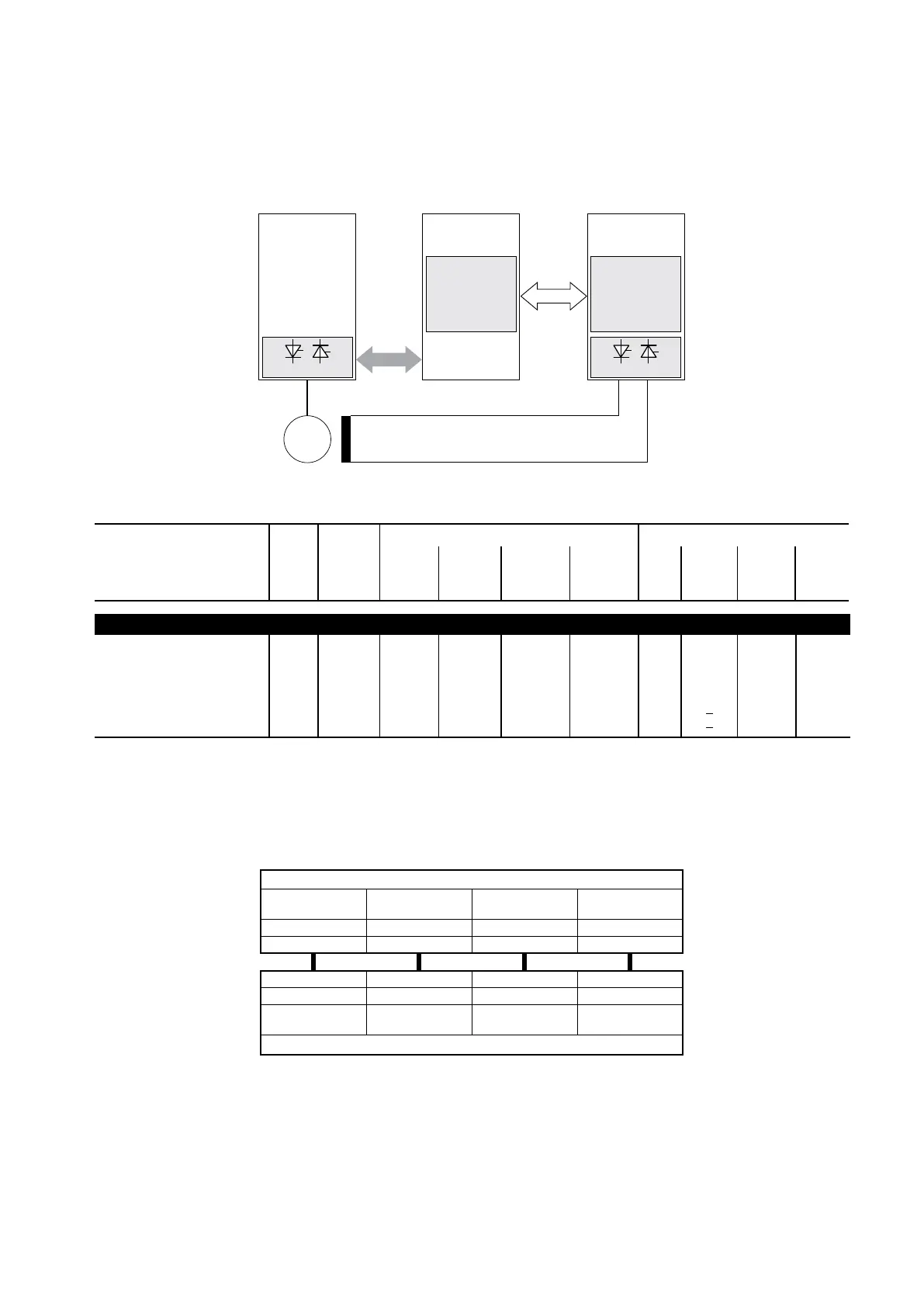
Figure A2.5.2: Block diagram of Field exciter control, connection via external I/Os
2Q / 4Q
R-TPD32
M
TPD32-EV-CU
Control Unit
TPD32-EV-FC
External Field
TPD32-EV-...-E
External Bridge
External I/O
R-TPD32
(1)
2Q / 4Q
Parameter No. Format
Value Access via
min max
Factory
American
Factory
European
Keyp.
RS485/
BUS/
Opt2-M
Term.
Opt2-A/
PDC
FLUX REGULATION (FIELD CURRENT REGULATION)
Fluxregmode
Constantcurrent
Voltagecontrol
External control
ExtdigitalFC
ExtwiredFC
469 U16 0 2 Const.
current
0
Const.
current
0
ü
R/Z
0
1
2
3
4
- -
SetFlux reg mode=Ext wired FC
eldcontrolbyTPD32-FCusingexternaldigitalandanalogI/Os.
(1) Recommended conguration for terminals
TPD32-EV / TPD32-EV-CU
IPA 66
Select output 1
IPA 139
Digital Input 3
IPA 138
Digital Input 2
IPA 137
Digital Input 1
[95] Field cur ref [90] Wired FC Act Brg [89] Wired FC Inv Seq [88] Wired FC EN
21 33 32 31
1 28 27 26
[6] T current ref 1 [82] Wired FC Act Brg [81] Wired FC Inv Seq [80] Wired FC EN
IPA 70
Select input 1
IPA 147
Digital Output 3
IPA 146
Digital Output 2
IPA 145
Digital Output 1
TPD32-EV-FC
 Loading...


