GMV5 Home DC Inverter Multi VRF Units
157
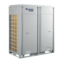
9.5.1.2.8 During refrigerant pipe installation, ensure a distance above 500 mm between the
pipe and the electric box of the unit for maintenance. In a case when the space is not enough, the
final piping way must be determined by the technical personnel.
9.4.1.2.9
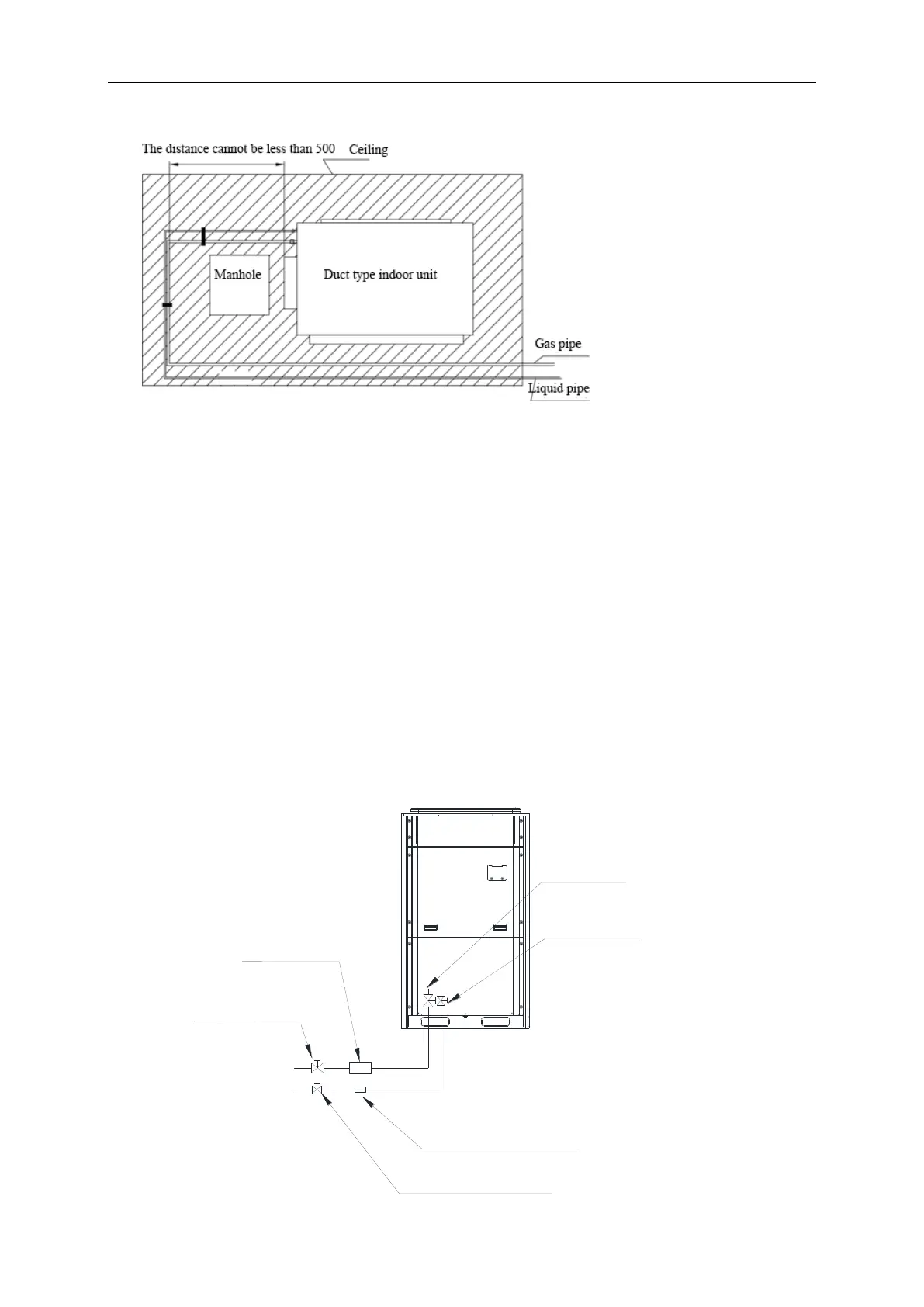
As the piping for the VRF system is complex, it is recommended that a filter is installed for the
gas pipe and a drier is installed for the liquid pipe during construction. This ensures aridity and
cleanness of the piping system and further improves the operation stability of the system.
The procedure is as follows:
First, weld a stop valve with the corresponding caliber to the gas pipe and liquid pipe at the
position relatively close to the ODU and easy for operation.
Second, install a filter (100 mesh/ft2) between the added stop valve outside the gas pipe and
the stop valve of the ODU. Then install a drier filter between the added stop valve outside the
liquid pipe and the stop valve of the ODU.
Lastly, after the test run is complete,
To remove the filter from the gas pipe after starting all IDUs and keeping them running cooling
mode for 24 hours: power off all units; turn off the two stop valves of the gas pipe; remove the filter;
short connect with a copper pipe with the same caliber and vacuumize the pipe; open the two stop
valves and keep normal running.
To remove the drier filter from the liquid pipe after starting all IDUs and keeping them running
in heating mode for 24 hours: power off all units; turn off the two stop valves of the liquid pipe;
remove the filter; short connect with a copper pipe with the same caliber and vacuumize the pipe;
open the two stop valves and keep normal running.
Drying filter for the liquid pipe
·
Added stop valve for the liquid pipe
Added stop valve
for the gas pipe
Gas pipe filter
Gas pipe stop valve equipped
to the outdoor unit
Liquid pipe stop valve equipped
to the outdoor unit
 Loading...