GMV5 Home DC Inverter Multi VRF Units
179
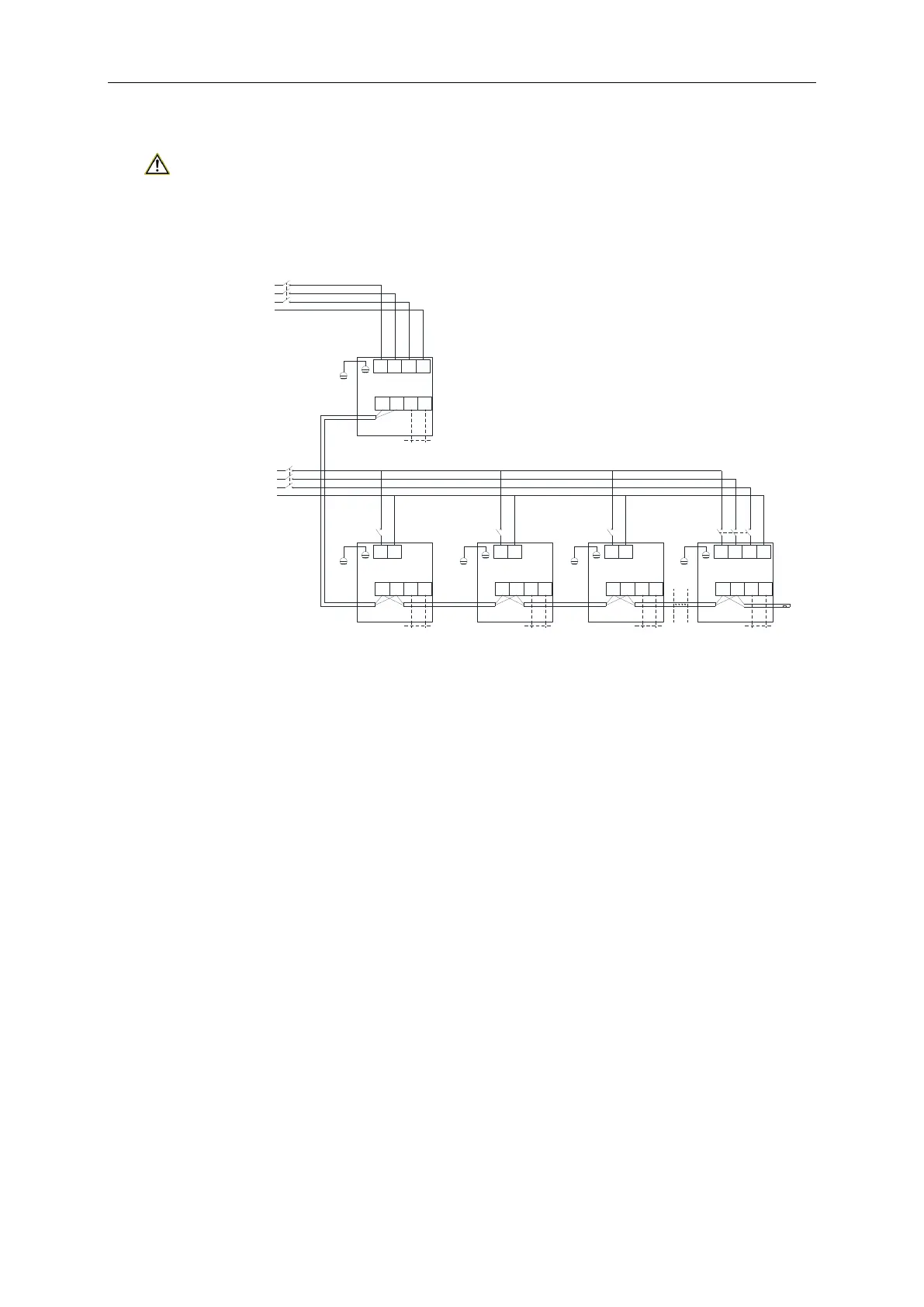
12.2.3 External wiring diagram of unit
12.2.3.1 ODU with hydro box and IDU
Note:
Each unit shall be equipped with a circuit breaker for shortcircuit and abnormal overload
protection. IDUs and ODU shall be set with the main circuit breaker separately, for connecting or
cutting off the main power.
L1 L2 L3 N
PE
PE
Power wiring board XT1
Power wiring board XT2
D1 D2 G1 G2
Long-distance monitoring
ODU
L1
L2
L3
N
Power supply
QF
L N
PE
PE
Power wiring board XT1
Power wiring board XT2
D1 D2 H1 H2
IDU 1
L1
L2
L3
N
Power supply
QF
L N
PE
PE
Power wiring board XT1
Power wiring board XT2
D1 D2 H1 H2
Hydro box
L N
PE
PE
Power wiring board XT1
Power wiring board XT2
D1 D2 H1 H2
Hydro box
L1 L2 L3 N
PE
PE
Power wiring board XT1
Power wiring board XT2
D1 D2 H1 H2
Wired controller
IDU n
Wired controllerWired controllerWired controller
QF QFQF QF
Connection wire
(resistance
matching)
12.2.3.2 Hydro box and water tank
(1)Electric wiring and connection
(1) Loosen the screws fixing the electric box cover on the hydro box. Open the electric box
cover.
(2) Connect one end of the electric heating power cable included on the water tank to the
terminal board of the main unit. The specific wiring terminal please refer to the wiring
diagram.
(3) Apply heat conductive silicone gel onto the water temperature sensor which leads out from
the hydro box, and then insert it into the lower water temperature sensor port at the lower
part of water tank. Connect the upper water temperature sensor included on water tank
(i.e. upper temperature sensor port in the middle of water tank) to the red connector
leading out from the terminal box on hydro box. Then, put it into electric box.
(4) Tighten the strong current cables with cable clamp and cover up the electric box.
(5) The wired controller shall be fixed properly. The communication wires from wired controller
and hydro box shall be correctly connected.
(6) Take care to route the strong current cables separately from the light current cables.
 Loading...