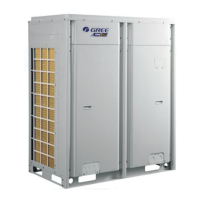
GMV5 Home DC Inverter Multi VRF Units
65
Auto mode (Under Auto mode, indoor units will automatically select their operating
mode as per the temperature change so as to provide comfort.)
Up and down swing function
Left and right swing function
Maximum and
minimum temperature
It's valid under Save mode and displays during setting.
Temperature lower limit for Cooling: Limit the minimum temperature value under
Cooling or Drying mode.
Temperature upper limit for Heating: Limit the maximum temperature value under
Heating, 3D Heating, Warming mode.
It shows the setting temperature value (If the wired controller controls a fresh air
blower, it will show "FAP").
Floor heating mode (When Heating and Floor Heating simultaneously show up, it
indicates 3D Heating is activated.)
Air exchange status. It's an optional function for indoor unit.
When inquiring or setting project number of indoor unit, it displays "No." icon.
Quiet status (including Quiet and Auto Quiet modes)
It displays "Set" icon under parameter setting interface.
It is displayed when light board of indoor unit is on.
It displays "Check" icon under parameter query interface.
It is displayed when Health function is set. It is an optional function for indoor unit.
It is displayed when Absence function is set.
Indoor unit is running in an energy-saving mode.
It indicates the current set fan speed (including 7 types of speed: Auto, Low
Speed, Medium-low Speed, Medium Speed, Medium-high Speed, High Speed
and Turbo Speed)
Gate-control card is out.
It indicates the current wired controller is a slave wired controller (address of wired
controller is 02).
It is displayed when operation is invalid.
Remind to clean the filter.
It is displayed when X-fan function is set.
Outdoor unit is running in energy-saving mode/System capacity upper limit is less
than 100%/Long-distance energy saving status
Allow auxiliary electric heating to be on.
It is displayed when one wired controller controls multiple indoor units.
Outdoor unit is in defrosting status.
Memory status (Indoor unit resumes the original setting state after power is
recovered from power failure).
It is displayed when the current wired controller connects the master indoor unit.
It displays system clock and timer status.
Remark: When wired controller is connected with different indoor unit, some function will be different.

 Loading...


