English (GB)
10
5. Operation and functions - LCD 107 two-pump
controller
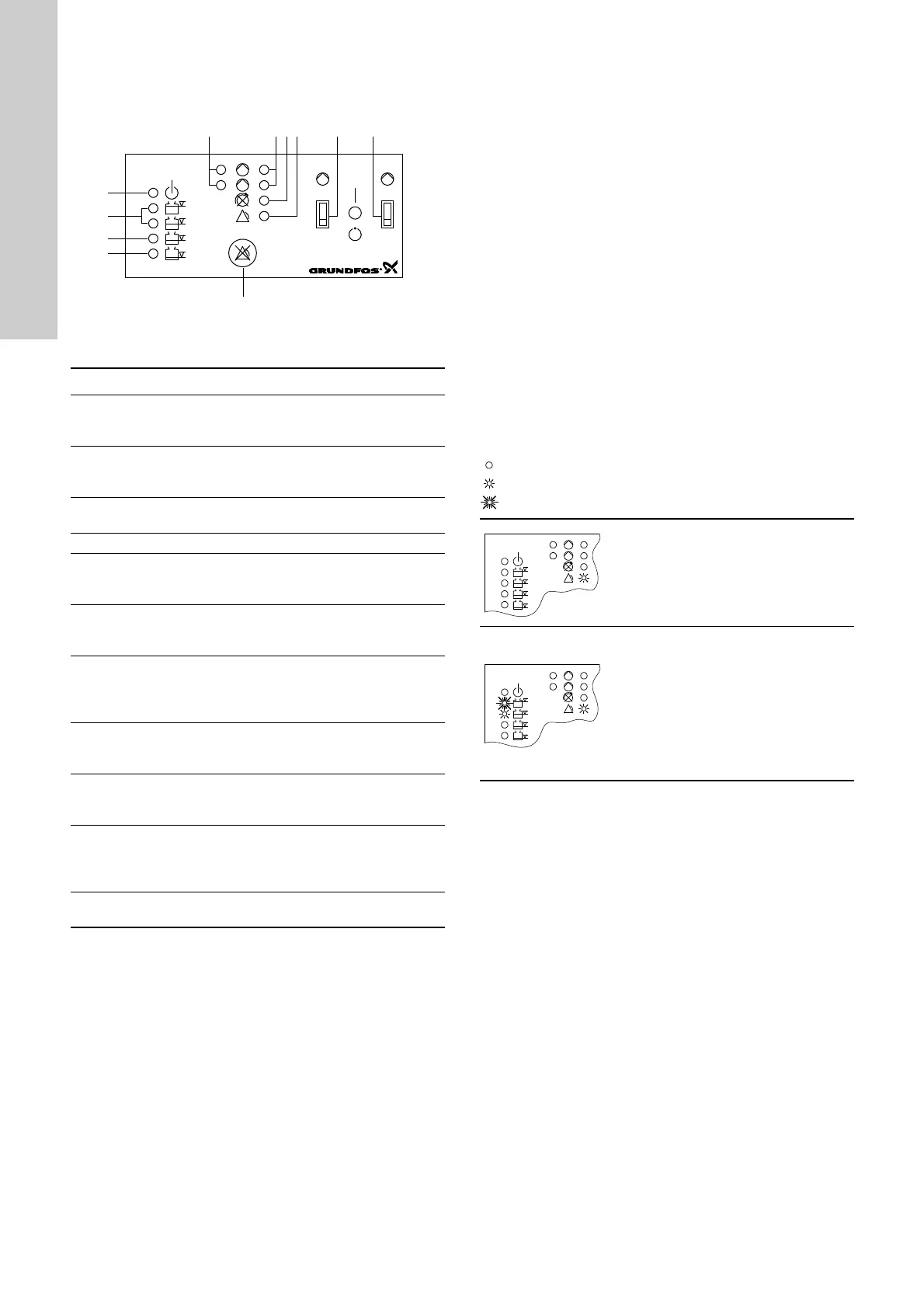
Figure 5 shows the control panel of the CU 212 module.
Fig. 5
Key to the symbols in fig. 5
5.1 Battery back-up functions - LCD 107 two-pump
controller
If a back-up battery for CU 212 (accessory) is installed, the
following functions will be carried out if the normal electricity
supply to the LCD 107 fails (see also the illustrations below):
• The common alarm is active, the red indicator light is on -
cannot be reset!
• If the external alarm device for common alarm is supplied from
an external power source, this device will be active - cannot be
reset by means of the reset button!
• The built-in buzzer is activated - can be reset by means of the
reset button!
• If the liquid level in the pit rises above the level for high-level
alarm, the top orange indicator light will be flashing and the
second orange indicator light from the top will be permanently
on.
• If the starting delay function and automatic test run were
selected (switch 4 of the DIP switch), the start-up will be
delayed after the electricity supply has been switched on when
the liquid level is sufficiently high, see section 2.5 Setting of
LC 107 and LCD 107.
The table below shows the two situations which may occur if the
normal electricity supply to the LCD 107 fails and a back-up
battery is installed:
= the indicator light is off.
= the indicator light is on.
= the indicator light is flashing.
TM01 4387 3703
Pos. Description
1
One green indicator light for each pump, indicating
starting delay (flashing) and pump operation
(permanently on).
2
One red indicator light for each pump
Flashing: Fault in PTC resistor/thermal switch
On: Fault in motor-protective circuit breaker.
3
Red indicator light, indicating wrong phase sequence
(three-phase pumps only).
4 Red indicator light, indicating common alarm.
5
ON-OFF-AUTO selector switch for pump 1, three
positions, see section 5.2 Reset button and ON-OFF-
AUTO selector switch - LCD 107 two-pump controller.
6
ON-OFF-AUTO selector switch for pump 2, three
positions, see section 5.2 Reset button and ON-OFF-
AUTO selector switch - LCD 107 two-pump controller.
7
Reset button, push-button for manual resetting of alarm
signals to external alarm devices and the built-in buzzer,
see section 5.2 Reset button and ON-OFF-AUTO
selector switch - LCD 107 two-pump controller.
8
Orange indicator light, which is activated by the bottom
level pickup. Indicating liquid level for start of the first
pump/common stop.
9
Orange indicator light, which is activated by the middle
level pickup. Indicating liquid level for start of the next
pump.
10
2 orange indicator lights, which are activated by the top
level pickup. In case of high-level alarm, the top
indicator light is flashing and the other is permanently
on.
11
Green indicator light, indicating that the electricity
supply has been switched on.
Mains supply failure:
• The common alarm is active.
The red indicator light is on.
• The green indicator light (electricity
supply switched on) is off.
Mains supply failure and high-level alarm:
• The common alarm is active.
The red indicator light is on.
• The top orange indicator light is
flashing.
• The second orange indicator light
from the top is on.
• The green indicator light (electricity
supply switched on) is off.

 Loading...