English (GB)
8
3. Start-up
Prior to start-up, the connection and DIP switch setting must have
been carried out according to sections 2.3 Connection of LC 107
one-pump controller, 2.4 Connection of LCD 107 two-pump
controller and 2.5 Setting of LC 107 and LCD 107.
Start-up must be carried out by authorized personnel.
Proceed as follows:
1. Check that the level pickups have been connected according
to the illustrations on page 95 or 96.
2. Check that the pump inlet is submerged in the liquid to be
pumped.
3. Set the motor protection relay(s) to the rated current stated on
the motor nameplate(s).
4. Switch on the electricity supply.
Three-phase pumps only: Check whether the phase
sequence is correct, (the pump(s) cannot be started if the
phase sequence is wrong!).
5. Start the pump(s), see section 4.2 Reset button and ON-OFF-
AUTO selector switch - LC 107 one-pump controller or
5.2 Reset button and ON-OFF-AUTO selector switch -
LCD 107 two-pump controller.
6. Check that the pump(s) is/are not running dry. The risk of dry
running can be eliminated by a renewed time setting by
means of the DIP switch (switches 5, 6 and 7) according to
section 2.5 Setting of LC 107 and LCD 107 and/or by moving
the level pickup.
7. Three-phase pumps only: Check that the direction of
rotation of the pump is correct according to the installation
and operating instructions for the pump in question.
8. Select the required operating mode by means of the ON-OFF-
AUTO selector switch, see section 4.2 Reset button and ON-
OFF-AUTO selector switch - LC 107 one-pump controller or
5.2 Reset button and ON-OFF-AUTO selector switch -
LCD 107 two-pump controller.
4. Operation and functions - LC 107 one-pump
controller
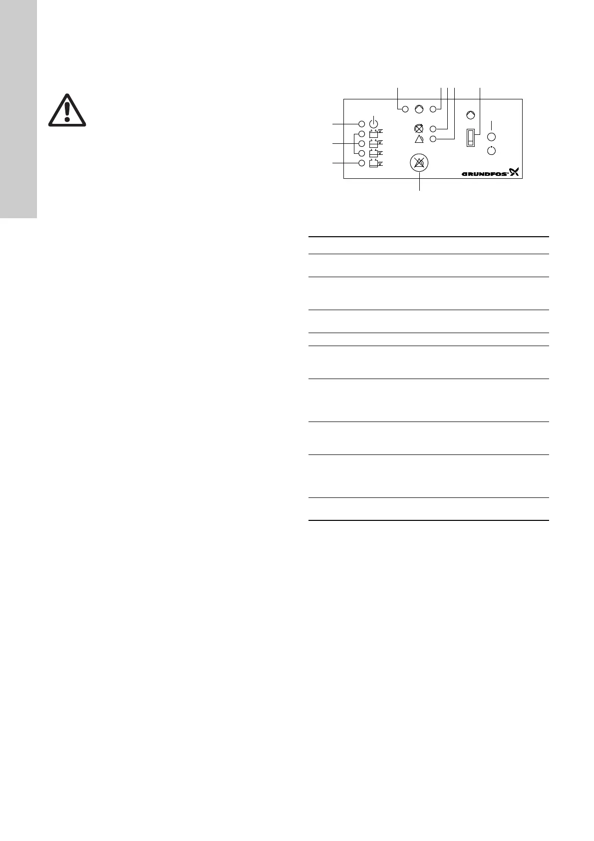
Figure 4 shows the control panel of the CU 211 module.
Fig. 4
Key to the symbols in fig. 4
Warning
Before starting any work on pumps used to pump
liquids which could be constituted as being
hazardous to health, thorough cleaning/venting of
pumps, pits, etc. must be carried out according to
local regulations.
Before making any connections in the LC/D 107 or
work on pumps, pits, etc., it must be ensured that the
electricity supply has been switched off and that it
cannot be accidentally switched on.
TM01 4860 3703
Pos. Description
1
Green indicator light, indicating starting delay (flashing)
and pump operation (permanently on).
2
Red indicator light, indicating pump fault
Flashing: Fault in PTC resistor/thermal switch
On: Fault in motor-protective circuit breaker.
3
Red indicator light, indicating wrong phase sequence
(three-phase pumps only).
4 Red indicator light, indicating common alarm.
5
ON-OFF-AUTO selector switch, three positions, see
section 4.2 Reset button and ON-OFF-AUTO selector
switch - LC 107 one-pump controller.
7
Reset button, push-button for manual resetting of alarm
signals to external alarm devices and the built-in buzzer,
see section 4.2 Reset button and ON-OFF-AUTO
selector switch - LC 107 one-pump controller.
8
Orange indicator light, which is activated by the lower
level pickup. Indicating liquid level for start/stop of
pump.
10
3 orange indicator lights, which are activated by the
upper level pickup. In case of high-level alarm, the top
indicator light is flashing and the two other orange
indicator lights are permanently on.
11
Green indicator light, indicating that the electricity
supply has been switched on.

 Loading...