English (GB)
5
2. Installation
The installation must be carried out by authorized personnel in
accordance with local regulations.
2.1 Location
LC/D 107 can be mounted at ambient temperatures ranging from
-30 °C to +50 °C.
Enclosure class: IP65.
When installed outdoors, the LC/D 107 must be placed in a
protective shed or cupboard.
LC/D 107 must not be exposed to direct sunlight.
2.2 Mounting
Before mounting, remove the transport protectors, if any, from
inside the cabinet.
Mount the LC/D 107:
• on a plane wall surface,
• with the Pg cable entries pointing downwards (additional Pg
cable entries, if required, must be fitted in the bottom plate of
the cabinet),
• with four screws through the mounting holes in the back plate
of the cabinet, see fig. 1. The mounting holes must be bored
with a 4 mm bore. Fit the screws into the mounting holes and
tighten securely. Fit the plastic caps supplied with the
controller on the screws (IP65).
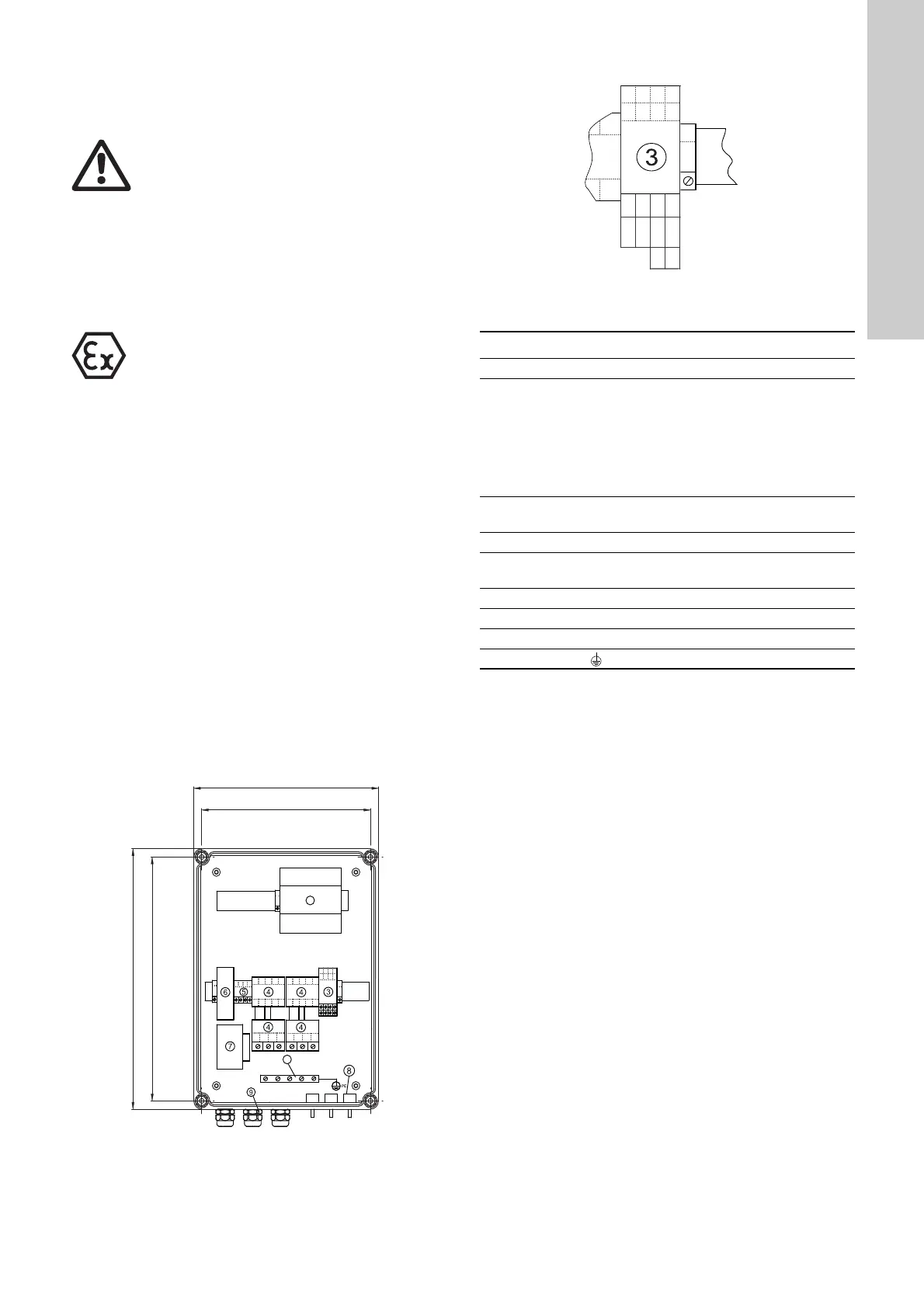
Figure 1 shows the internal construction of the LCD 107
(the LC 107 is constructed in the same way).
Fig. 1
Figure 2 shows the terminals listed under position 3.
Fig. 2
Key to the symbols in figs 1 and 2:
Note: Maximum length of the pressure hoses for the bell-shaped
level pickups is 20 metres.
Warning
Before starting any work on pumps used to pump
liquids which could be constituted as being
hazardous to health, thorough cleaning/venting of
pumps, pits, etc. must be carried out according to
local regulations.
Before making any connections in the LC/D 107 or
work on pumps, pits, etc., it must be ensured that the
electricity supply has been switched off and that it
cannot be accidentally switched on.
Warning
The LC/D 107 controller must not be installed in
explosion hazard areas. Only the level pickups can
be installed in explosion hazard areas.
TM01 4783 0500
TM01 4832 0999
Pos. Description
1 Module CU 212 for LCD (module CU 211 for LC).
3
Terminal block with:
• inputs for the PTC resistance/thermal switch of the
motor (T11-T21, T12-T22),
• output for external alarm device for high-level alarm
(H-NC, H-COM, H-NO),
• output for external alarm device for common alarm
(G-NC, G-COM, G-NO).
4
Motor protection relays, pumps 1 and 2 (contacts and
thermal relay fitted).
5 Terminal block for electricity supply.
6
Fuse holders for control circuit fuses
(1 to 3 depending on voltage/current variant).
7 Isolating transformer (for LCD only).
8 Pressure switch for level input.
9 Pg cable entries.
10 Earth bar (
PE
).
T22
T12
T21
T11
H-NO
H-COM
H-NC
G-NO
G-COM
G-NC

 Loading...