English (GB)
4
English (GB) Installation and operating instructions
Original installation and operating instructions
CONTENTS
Page
1. General
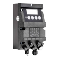
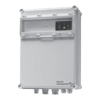
The designation LC/D 107 used in the following refers to the
pump controllers LC 107 and LCD 107.
LC/D 107 is designed for the control of pumps in wastewater
pumping systems.
Type key
1.1 Applications
LC/D 107 enables:
• control of 1 or 2 pumps based on signals from bell-shaped
level pickups,
• automatic pump changeover (even distribution of operating
hours on both pumps),
• selection of automatic test run during long periods of inactivity
(every 24 hours),
• battery back-up in case of mains supply failure (accessory),
• starting delay within the range from 0 to 255 sec. (random)
after returning from battery operation to mains operation
(resulting in an even mains load when several pumping
stations are started up at the same time),
• selection of automatic alarm resetting,
• selection of automatic restarting,
• setting of stop delays matching the actual operating
conditions,
• indication of liquid level,
• alarm indication of:
– too high liquid level, which triggers a high-level alarm,
– overload (via motor protection relay),
– overtemperature (via PTC resistance or thermal switch in
motor),
– wrong phase sequence,
– mains supply failure,
– failing level pickup.
As standard, the LC/D 107 has two alarm signal outputs:
• common alarm,
• high-level alarm.
Furthermore, the controller incorporates a buzzer.
1.2 Variants
The actual controller type, voltage variant, etc. are stated in the
type key on the nameplate situated on the side of the controller
cabinet.
LC 107 for wastewater pits with 1 pump and 2 bell-shaped level
pickups as shown in fig. 1 on page 95.
LCD 107 for wastewater pits with 2 pumps and 3 bell-shaped
level pickups as shown in fig. 4 on page 96.
1. General
4
1.1 Applications
4
1.2 Variants
4
2. Installation
5
2.1 Location
5
2.2 Mounting
5
2.3 Connection of LC 107 one-pump controller
6
2.4 Connection of LCD 107 two-pump controller
6
2.5 Setting of LC 107 and LCD 107
7
3. Start-up
8
4. Operation and functions - LC 107 one-pump
controller
8
4.1 Battery back-up functions - LC 107 one-pump controller
9
4.2 Reset button and ON-OFF-AUTO selector switch -
LC 107 one-pump controller
9
5. Operation and functions - LCD 107 two-pump
controller
10
5.1 Battery back-up functions - LCD 107 two-pump
controller
10
5.2 Reset button and ON-OFF-AUTO selector switch -
LCD 107 two-pump controller
11
6. Fault finding chart
12
7. Maintenance
13
8. Technical data
13
9. Disposal
13
Warning
Prior to installation, read these installation and
operating instructions. Installation and operation
must comply with local regulations and accepted
codes of good practice.
Example LC 107 400 3 2.9
LC = one-pump controller
LCD = two-pump controller
107 = type designation
Phase voltage [V]
1 = single-phase
3 = three-phase
Maximum operating current per pump [A]
 Loading...
