5. Assembly
PNEG-750-G2 16" Series II Sweep 131' and 135' Diameter 33
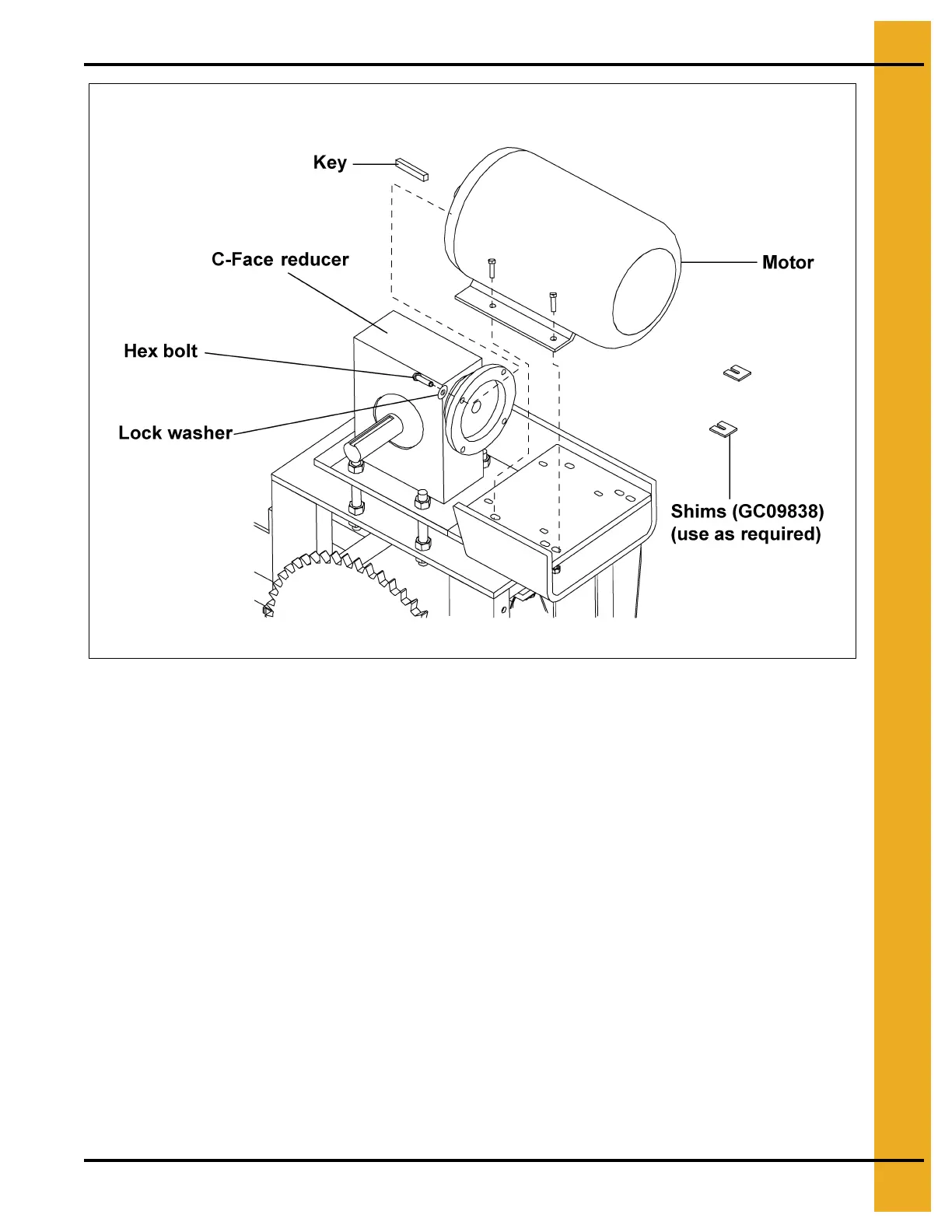
Figure 5P
Guard Assembly
A. Attach the guard plate to the tractor drive stand legs using 3/8" bolts and nuts before attaching the
drive sprocket. (See Figure 5Q on Page 34.)
B. Slide the fourteen (14) tooth (teeth N/S) drive sprocket, bushing and key (see key chart on
Page 34 for the size key) onto the output shaft of the reducer, make sure both sprockets line up.
(See Figure 5Q and Figure 5Q_A on Page 34.)
C. Assemble the bottom chain guard trap to the bottom chain guard weldment using 1/2" x 3" HHCS
bolts, 1/2" split lock washers and 1/2" hex nuts.
(See Figure 5Q on Page 34.)
D. Attach bottom chain guard weldment to tractor drive stand using 3/8" x 1-1/4" HHCS bolts,
3/8" split lock washers and 3/8" hex nuts. (See Figure 5Q on Page 34.)
E. Attach top chain guard assembly to tractor drive stand using 3/8" x 1" bolts, 3/8" split lock washers
and 3/8" hex nuts. (See Figure 5Q on Page 34.)
182TC Frame Four (4) 1/2"-13 x 1-1/4" hex bolts and 1/4" x 1/4" x 1" key
NOTE:
 Loading...