19
4 - System setup
Tractor installation
Control units
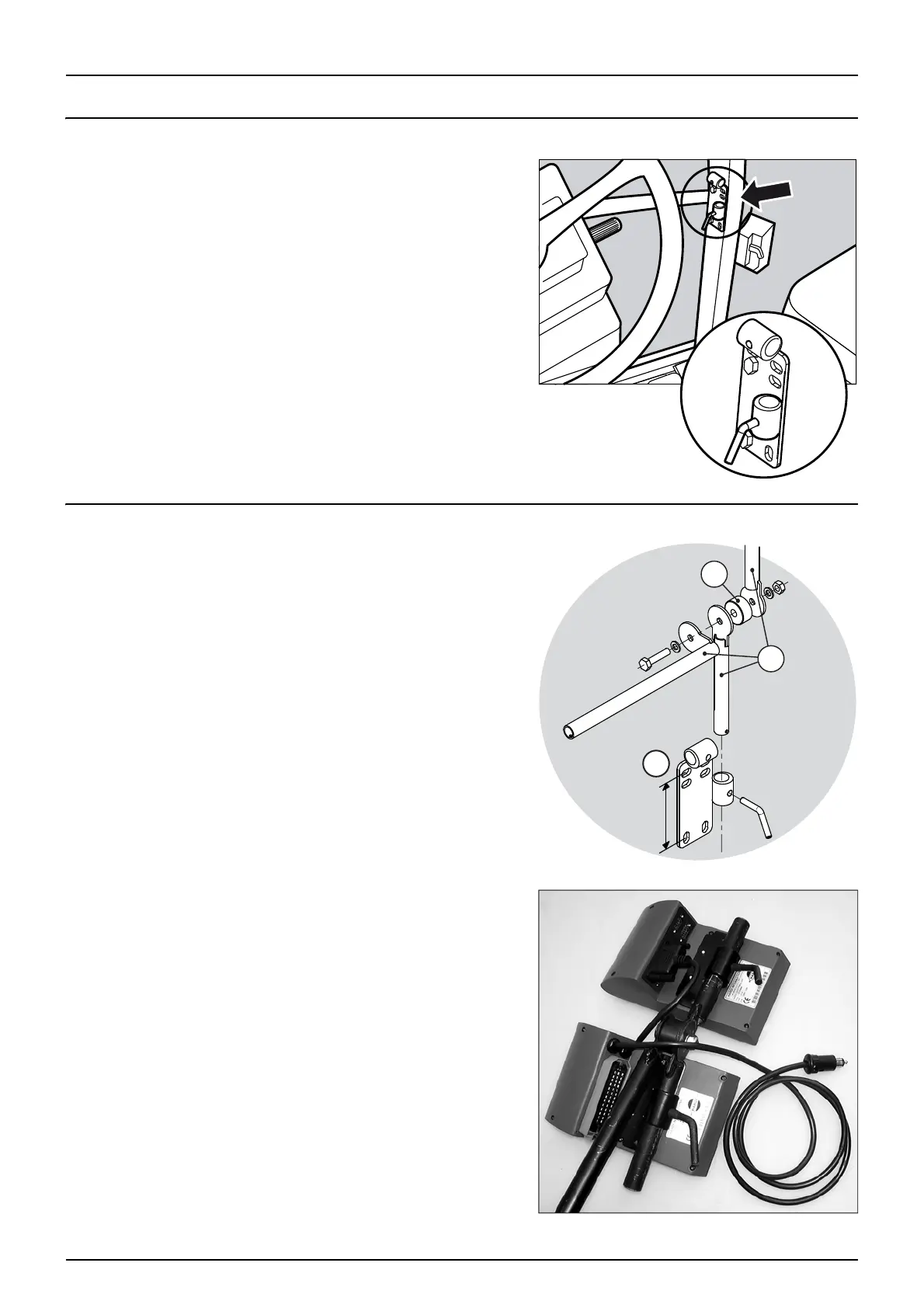
Find a suitable place in the tractor’s cabin to secure the control units
from movement. Best recommended placement is to the right of the
driver seat. The supplied bracket will fit most tractors. Threaded
mounting holes may be hidden behind front corner cover.
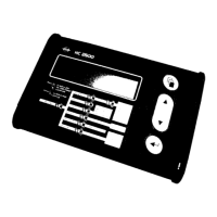
Installation of control unit brackets
The supplied tractor pillar bracket (A) has a hole spacing of 100 and 120
mm. Check tractor instructions manual for information regarding
attachment points.
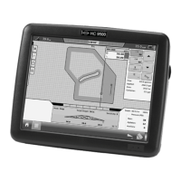
Three tubes (B) are supplied. One, two or all 3 may be used. They can be
bent and shortened. A spacer (C) is also supplied to allow further
attachment possibilities. Find the best solution for your tractor or
vehicle.
Tube (B) plate is staggered so if correctly orientated, all boxes will line up.
The recommended setup is to place the spacer (C) between the two
tubes (B) used for the controllers and the 3rd tube (B) which is to be
mounted in the bracket (A), as shown on the picture.
μ
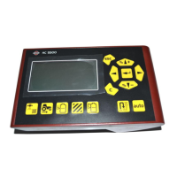
ATTENTION! An extension cable is available as an option if the HC
5500 control unit is to be placed further away from the EFC
control unit. (Ref. no. 261933)
 Loading...