Note
The number of vertexes should be consistent with the selected number of Calibraon Point.
4) Drag the vertexes of the calibraon area to align it to the lanes.
Note
●
If the lanes cannot be aligned, ensure the calibraon area can contain the detecon area.
●
You can refer to the schemac diagram and top view descripon to draw the calibraon
area.
5) Oponal: Click Clear to clear the drawn calibraon area.
3.
Measure the world coordinates of the vertexes, and enter the values in the corresponding
coordinate text elds.
Note
The origin (0, 0) of the world coordinates locates in the middle of the whole lanes detected by
the radar. You can refer to the top view of the diagram for the posions.
4.
Enter Linearity Correcon and Constant Correcon.
Linearity Correcon
Enter the value to adjust the speed detecon result via video according to the actual speed.
Constant Correcon
The constant correcon is to improve the accuracy of the detecon speed. It is the extra
added/minus speed value.
Note
The nal speed is calculated according to the video output speed, the linearity correcon, and
constant correcon together. E.g., the detected speed is 80 km/h, and you set the linearity
correcon as 1.2, and the constant correcon as 5, then the nal speed is 80 km/h × 1.2 + 5 =
101 km/h. And if you do not want to make any change to the detected speed, you can set the
linearity correcon as 1, and the constant correcon as 0.
5.
Oponal: Check Hide Calibraon Lines to hide the lines on the live view image.
6.
Click OK.
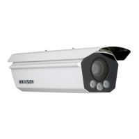
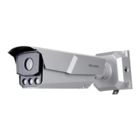
1.7.6 Set Radar Parameters
Set radar parameters for speed
detecon via radar.
Steps
Note
●
Not all the applicaon modes support radar parameters.
●
The radar parameters vary with dierent models. The actual device prevails.
Network Trac Camera Conguraon Manual
36
 Loading...