Excel 800 LION
EN1B-0375GE51 R0308
34
CLLIONLC01 Terminals
74
14 10 7
73
13 9 6
72
12
8 5
71
11
24
V~
24
V~0
LON
2
C- C
C+ C
LON
2
LON
1
LON
1
V
V
24
V~0
COM
B
COM
B
COM
A
COM
A
SHIELD SHI
87 6
5
4 32 1
*Watch
Rela
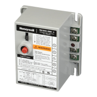
Fig. 47 Terminal assignment and internal connections of
the CLLIONLC01
Controller Module
Ter-
minal
Signal Comment
71, 75 COM a
2-wire communication bus
(LON/Panel Bus)
72, 76 COM b
2-wire communication bus
(LON/Panel Bus)
73, 77 24 V~ Power supply for I/O modules
74, 78 24 V~0
Power supply for I/O modules
1 24 V~ Power supply from transformer
2 24 V~0
Power supply from transformer
3 24 V~0
Alarm/watchdog output
4 NC Alarm/watchdog output
5, 8 C+ C-Bus
6, 9 C- C-Bus
7, 10 Shield C-Bus shield
11, 12 LON L
ON
W
ORKS
IN
13, 14 LON L
ON
W
ORKS
OUT
Table 27 Description of CLLIONLC01 terminals
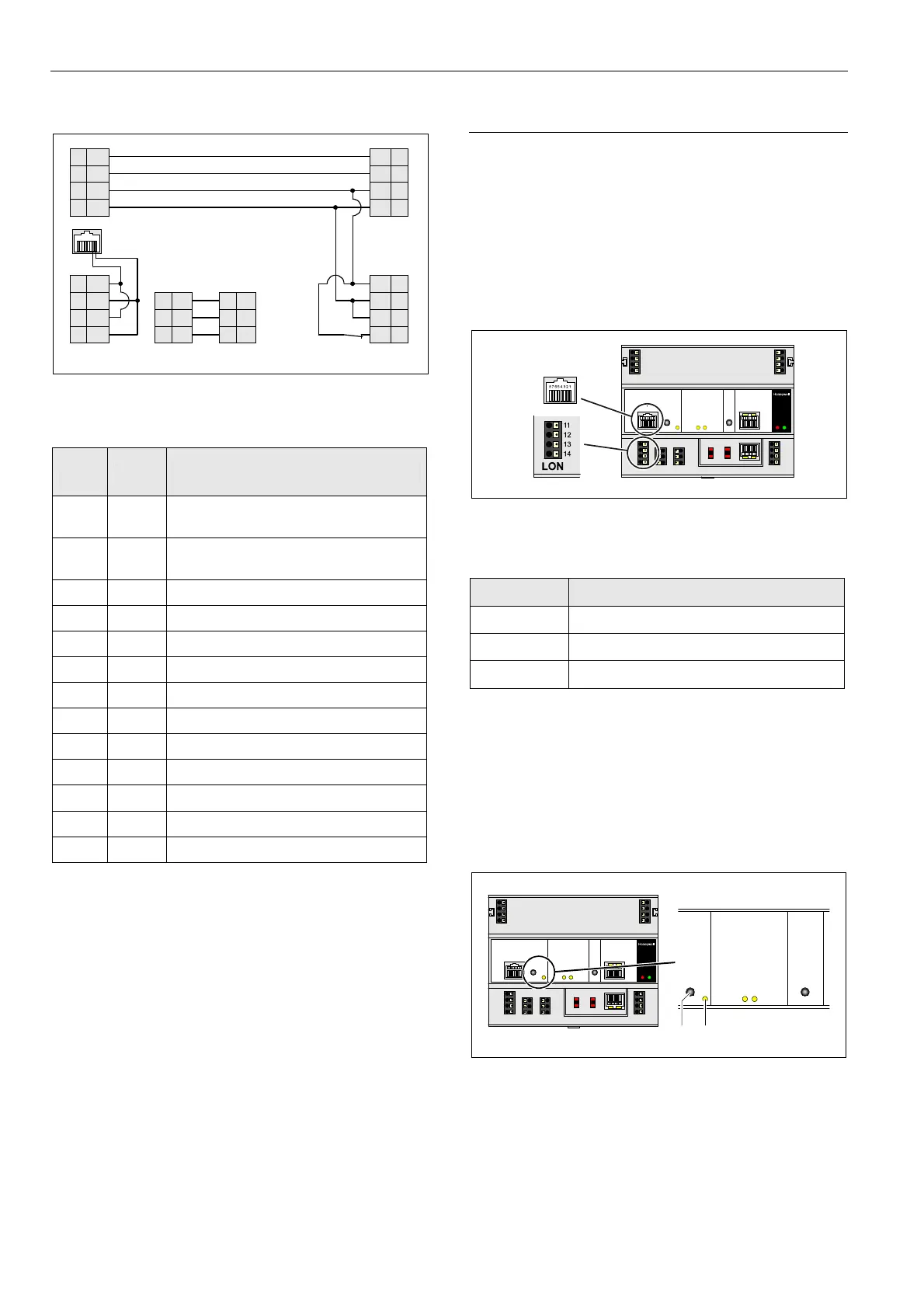
Features
L
ON
W
ORKS
Interface and Terminals
The CLLIONLC01
Controller Module features
• An RJ45 socket serving as an interface
to connect laptops or HMIs to the L
ON
W
ORKS
Bus
• L
ON
W
ORKS
terminals 11, 12, 13, and 14
to connect L
ON
W
ORKS
Bus I/O modules or other
L
ON
W
ORKS
devices to the CLLIONLC01 Controller or
other L
ON
W
ORKS
controllers.
Fig. 48 L
ON
W
ORKS
interface and L
ON
W
ORKS
terminals
L
ON
W
ORKS
Interface Signals on RJ45 Socket
Pin Signal type
1 Connection to L
ON
W
ORKS
Bus
2 Connection to L
ON
W
ORKS
Bus
3 … 8 Not used
Table 28 Signals of L
ON
W
ORKS
interface
L
ON
W
ORKS
Service LED and Button
The CLLIONLC01
Controller Module is equipped with a
L
ON
W
ORKS
service button and corresponding L
ON
W
ORKS
Service LED (status: yellow/OFF).
1
LON
2
Fig. 49 L
ON
W
ORKS
service button (1) and service LED (2)
See also section "Troubleshooting" on page 68.

 Loading...