LYNX Touch Installation and Setup Guide
- 10 -
Installing/Configuring Communication & Home Automation Modules
General
This LYNX Touch control supports central station reporting using wireless (GSM) and hardwire (IP)
communications modules. It also supports upload/download programming capability via the Internet or a
Private local area network (Intranet). This allows site maintenance independent of central station
monitoring, and modification to sites globally via the Internet or through a private LAN. Refer to the
instructions provided with the LRR/IP Communications Module being installed for additional information
regarding its installation, programming, and registration. The control is compatible with the following
AlarmNet Communications Modules:
• GSMVLP5-4G/GSMVLP5CN4G GSM Communication Module
• ILP5 Ethernet Communications Module
Communications Module 24-Hour Standby Power
If you require 24-hour standby, you must install the Super High Capacity battery P/N LYNX-RCHB-SHA in
the control.
!
RF Exposure
WARNING: The LYNX Touch must be installed to provide a separation distance of at least 7.8 in (20 cm) from all
persons and not co-located or operated in conjunction with any other transmitter except in accordance with FCC
multi-transmitter product procedures.
Connecting and Configuring Communication Modules
Connect and configure the communications module as follows:
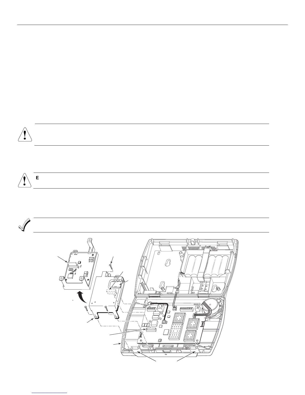
Installing the GSMVLP5-4G/GSMVLP5CN4G
!
Ensure that SIM card and the connector board are securely installed in the GSMVLP5-4G/GSMVLP5CN4G
before installing the communications module in the LYNX Touch.
1. Install the GSMVLP5-4G/GSMVLP5CN4G into the LYNX Touch control front case. Ensure that the connector board is properly seated
into the receptacle on the control.
2. Secure the GSMVLP5-4G/GSMVLP5CN4G with the three provided screws.
3. Enable the GSMVLP5-4G/GSMVLP5CN4G device, configure alarm reporting and module supervision and register the device. Refer to
the “Program the Communications Module” and “Communications Diagnostics” sections.
The communications module must be registered with AlarmNet before downloading or alarm reporting can
take place.
SCREW
(3)
SIM
CARD
5000-100-151-V2
ROTATED
180
CONNECTOR
BOARD
CONNECTOR
BOARD
RECEPTACLE
GSMVLP5-4G/
GSMVLP5CN4G
LYNX TOUCH
LOCKING TABS
 Loading...