66
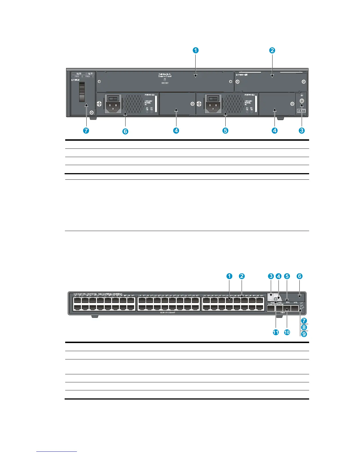
Figure 70 Rear panel
(1) OAP card slot
(3) Grounding screw (4) Filler modules
(5) Power supply slot 1 (6) Power supply slot 2
(7) Hot swappable fan tray
NOTE:
• The 5800-48G-PoE+ (2 slots) and 5800-48G-PoE+ TAA (2 slots) switches come with power supply slo
1 empty and power supply slot 2 installed with a filler panel. You can install one or two power supplies
for the switch as needed. In this figure, two PSR300-12A AC power supplies are installed in the slots.
• These two switches also come with the PoE module slot and the OAP card slot covered by filler panels.
In this figure, a PoE module is installed.
5800-48G (1 slot)/5800-48G TAA (1 slot)
Figure 71 Front panel
(1) 10/100/1000Base-T auto-sensin
(2) 10/100/1000Base-T Ethernet port LED
ment LED (4) Port mode LED
(5) SFP+ port LED (6) Logo plate (A console port and a USB port are
under this lo
o plate)
(7) System status LED (SYS) (8) RPS status LED (RPS)
(9) Interface card status LED (SLOT1)
(11) Port LED mode switching button
To use the console port and USB port, open the logo plate, as shown in Figure 72.
 Loading...


