73
5800-24G-SFP (1 slot)/5800-24G-SFP TAA (1 slot)
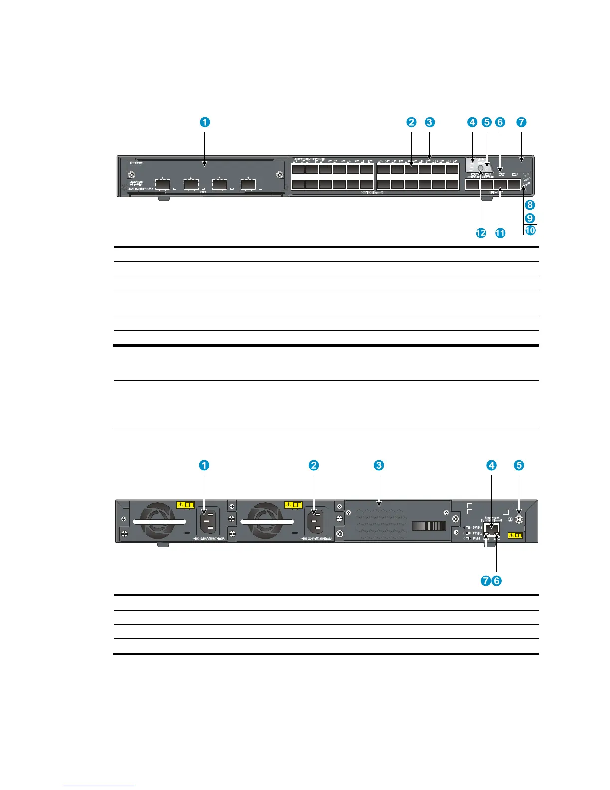
Figure 84 Front panel
(1) Interface card slot (2) 100/1000Base-X SFP port
(3) 100/1000Base-X SFP port LED (4) Seven-se
(5) Port mode LED (6) SFP+ port LED
(7) Logo plate (A console port and a USB port are
under this lo
o plate)
(8) System status LED (SYS)
(9) Power supply 1 status LED (PWR1)
(10) Power supply 2 status LED (PWR2)
(11) SFP+ port (12) Port LED mode switching button
To use the console port and USB port, open the logo plate, as shown in Figure 72 and Figure 73.
NOTE:
The 5800-24G-SFP (1 slot) and 5800-24G-SFP TAA (1 slot) switches come with the expansion interface
card slot covered by a filler panel. In this figure, an LSW1SP4P0 interface card is installed in the slot.
Figure 85 Rear panel
(1) Power supply slot 1 (2) Power supply slot 2
(3) Hot swappable fan tray (4) Management Ethernet port
(5) Groundin
(7) LINK LED for the mana
 Loading...


