75
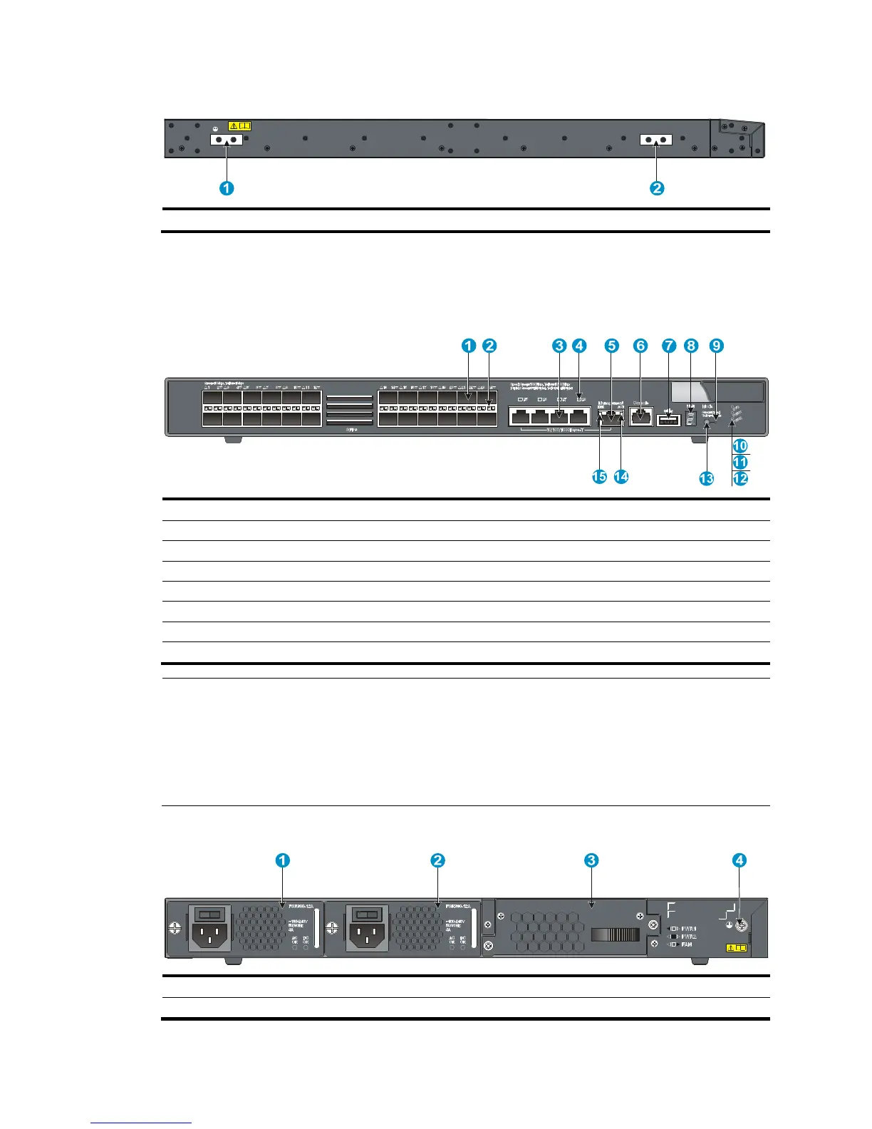
Figure 88 Left side panel
(1) Primary grounding point (2) Auxiliary grounding point 1
5820X-24XG-SFP+/5820X-24XG-SFP+ TAA
Figure 89 Front panel
(1) SFP+ port (2) SFP+ port LED
(3) 10/100/1000Base-T auto-sensin
(4) 10/100/1000Base-T Ethernet port LED
(5) Management Ethernet port (6) Console port
(7) USB port (8) Seven-se
(10) System status LED (SYS)
(11) Power supply 1 status LED (PWR1) (12) Power supply 2 status LED (PWR2)
(13) Port LED mode switchin
(15) LINK LED for the mana
NOTE:
• The SFP+ ports are numbered from left to right and from top to bottom, with you facing the front panel.
The first top left SFP+ port is numbered 1, the first bottom left SFP+ port is numbered 2, the second top
left port is numbered 3, and so on.
• The 10/100/1000Base-T auto-sensing Ethernet ports, from left to right, are numbered 25, 26, 27, and
28.
Figure 90 Rear panel
(1) Power supply slot 1 (2) Power supply slot 2
(3) Hot swappable
 Loading...


