53
Appendix D Cooling system
The cooling system of the HP 5920 and 5900 switches comprises the ventilation holes in the chassis, fan
trays, and built-in fans of hot swappable power supplies. To guarantee that this cooling system can
effectively work, you must consider the site ventilation design when you plan the installation site for the
switches.
HP 5920AF-24XG cooling system
The fan trays in the HP 5920AF-24XG and 5920AF-24XG TAA switches must be the same type:
LSVM1FANSC or LSVM1FANSCB.
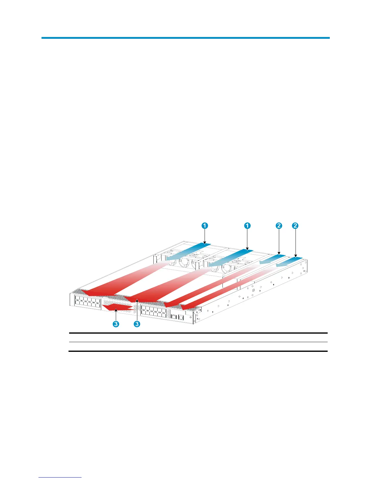
• When LSVM1FANSC fan trays are used, cool air flows in through the air vents in the fan tray panel
and the power supply panels, circulates through the chassis and the power supplies, and exhausts
at the network port side, as shown in Figure 55.
• W
hen LSVM1FANSCB fan trays are used, cool air flows in through the air vents in the network
port-side panel and the power supply panels, circulates through the chassis and the power supplies,
and exhausts through the air vents in the fan tray panels, as shown in Figure 56.
Figure 53 Airflow through the chassis (with LSVM1FANSC fan tr
ays)
(1) Fan tray air vents (2) Power supply air vents
(3) Network port-side air vents
 Loading...