EasyManuals Logo
Home>HP>Switch>5920 Series

HP 5920 Series Installation Guide

HP 5920 Series
63 pages
To Next Page IconTo Next Page
To Previous Page IconTo Previous Page
Page #6 background imageLoading...
Page #6 background image
2
HP 5920AF-24XG/HP 5920AF-24XG TAA panel
views
Figure 1 HP 5920AF-24XG/HP 5920AF-24XG TAA front panel
(1) SFP+ port (2)
SFP+ port LED
(3) Mana
g
ement Ethernet port (4) Console port
(5) System status LED (SYS) (6) ACT LED for the management Ethernet port
(7) LINK LED for the mana
g
ement Ethernet port
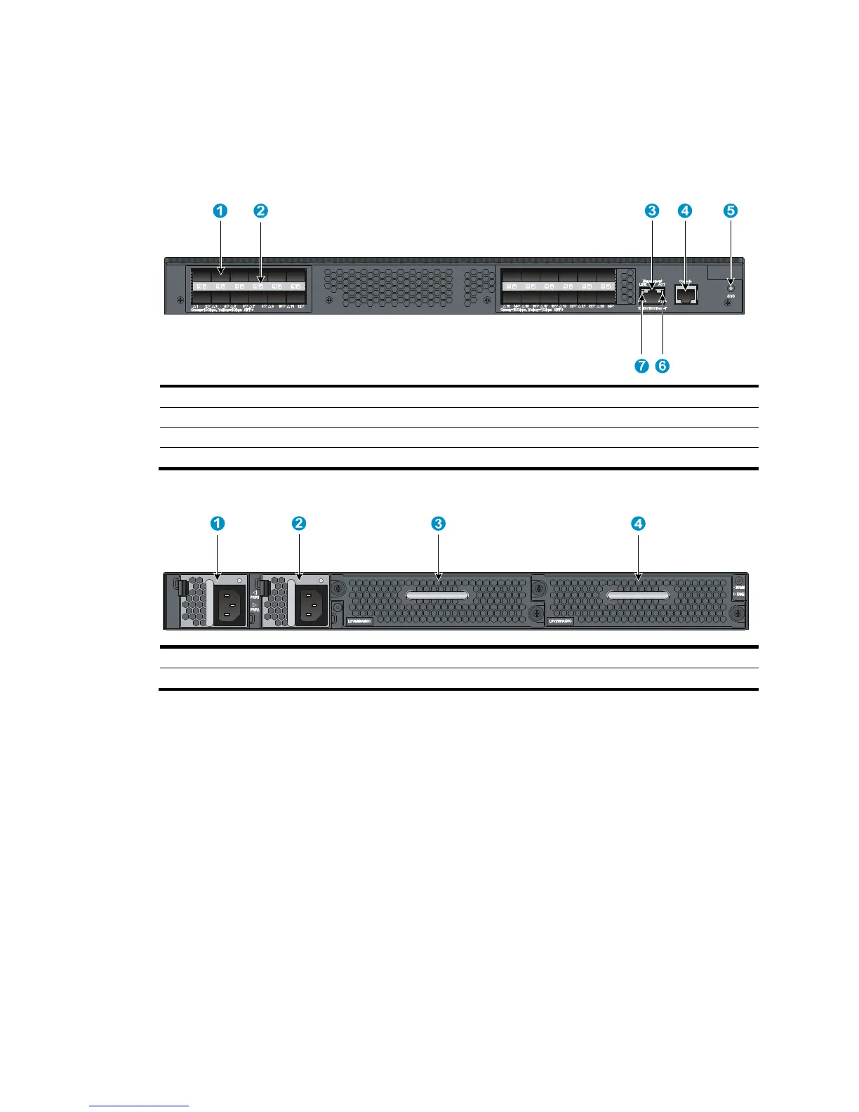
Figure 2 HP 5920AF-24XG/HP 5920AF-24XG TAA rear panel
(1) Power supply slot 1 (2) Power supply slot 2
(3) Fan tray slot 1
(4) Fan tray slot 2
The HP 5920AF-24XG and 5920AF-24XG TAA switches come with the power supply slots empty and the
filler modules for the slots as accessories. You can install one or two power supplies for the switch as
needed. In this figure, two 650W AC power supplies are installed. For more information about installing
and removing the power supply, see "Installing/removing a power supply."
T
he HP 5920AF-24XG and 5920AF-24XG TAA switches also come with the fan tray slots empty. You must
install two fan trays for the 5920AF-24XG and 5920AF-24XG TAA for adequate heat dissipation, and
their models must be the same. In this figure, two LSVM1FANSC fan trays are installed. For more
information about installing and removing the fan tray, see "Installing/removing a fan tray."

Table of Contents

Other manuals for HP 5920 Series

Questions and Answers:

Question and Answer IconNeed help?

Do you have a question about the HP 5920 Series and is the answer not in the manual?

HP 5920 Series Specifications

General IconGeneral
BrandHP
Model5920 Series
CategorySwitch
LanguageEnglish

Related product manuals