EasyManuals Logo
Home>HP>Switch>5920 Series

HP 5920 Series Installation Guide

HP 5920 Series
63 pages
To Next Page IconTo Next Page
To Previous Page IconTo Previous Page
Page #9 background imageLoading...
Page #9 background image
5
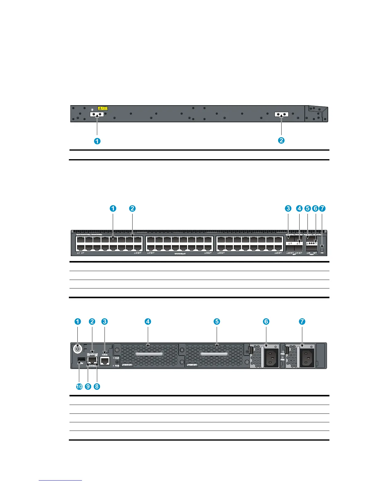
11, two LSVM1AC650 power supplies are installed. For more information about installing and removing
the power supply, see "Installing/removing a power supply."
The HP 5900AF-48XGT-4QSFP+ switch also comes with the fan tray slots empty. You must install two fan
trays for the 5900AF-48XGT-4QSFP+ for adequate heat dissipation, and their models must be the same.
In Figure 11, t
wo LSWM1HFANSC fan trays are installed. For more information about installing and
removing the fan tray, see "Installing/removing a fan tray."
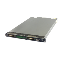
Figure 9 H
P 5900AF-48XGT-4QSFP+ left side panel
(1) Primary grounding point (2) Auxiliary grounding point 1
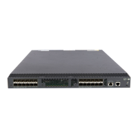
HP 5900AF-48G-4XG-2QSFP+ panel views
Figure 10 HP 5900AF-48G-4XG-2QSFP+ front panel
(1) 10/100/1000Base-T autosensin
g
Ethernet port
(2) 10/100/1000Base-T
autosensin
g
Ethernet port LED
(3) SFP+ port (4) SFP+ port LED
(5) QSFP+ port (6) QSFP+ port LED
(7) System status LED (SYS)
Figure 11 HP 5900AF-48G-4XG-2QSFP+ rear panel
(1) Groundin
g
screw (auxiliary
g
roundin
g
point 2)
(2) Mana
g
ement Ethernet port
(3) Console port (4) Fan tray slot 1
(5) Fan tray slot 2 (6) Power supply slot 1
(7) Power supply slot 2 (8) LINK LED for the mana
g
ement Ethernet port
(9)
A
CT LED for the mana
g
ement Ethernet port
(10) USB port

Table of Contents

Other manuals for HP 5920 Series

Questions and Answers:

Question and Answer IconNeed help?

Do you have a question about the HP 5920 Series and is the answer not in the manual?

HP 5920 Series Specifications

General IconGeneral
BrandHP
Model5920 Series
CategorySwitch
LanguageEnglish

Related product manuals