54
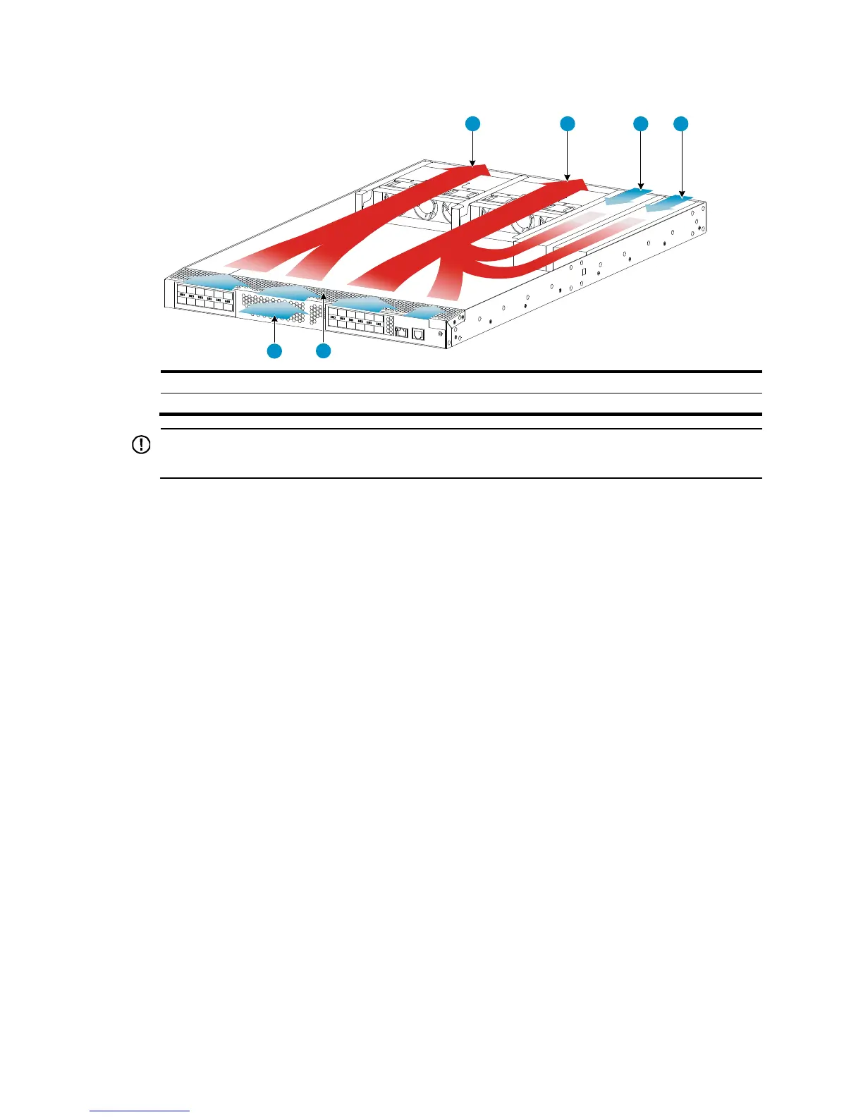
Figure 54 Airflow through the chassis (with LSVM1FANSCB fan trays)
(1) Fan tray air vents (2) Power supply air vents
(3) Network port-side air vents
IMPORTANT:
The chassis and the power supplies use separate air aisles. Make sure both aisles are not blocked.
HP
5900AF-48XG-4QSFP+/5900AF-48XG-4QSFP+
TAA/HP
5900AF-48XGT-4QSFP+/5900AF-48G-4XG-2QS
FP+ cooling system
The fan trays in the HP 5900AF-48XG-4QSFP+, 5900AF-48XG-4QSFP+ TAA, and
5900AF-48G-4XG-2QSFP+ switches must be the same type: LSWM1FANSC or LSWM1FANSCB.
The fan trays in the HP 5900AF-48XGT-4QSFP+ switch must be the same type: LSWM1HFANSC or
LSWM1HFANSCB.
• When LSWM1FANSC/LSWM1HFANSC fan trays are used, cool air flows in through the air vents
in the fan tray panel and the power supply panels, circulates through the chassis and the power
supplies, and exhausts at the network port side, as shown in Figure 55.
• W
hen LSWM1FANSCB/LSWM1HFANSCB fan trays are used, cool air flows in through the air
vents in the network port-side panel and the power supply panels, circulates through the chassis
and the power supplies, and exhausts through the air vents in the fan tray panels, as shown
in Figure 56.
3
3
1 1 2 2
 Loading...