Pulse Profile Domain
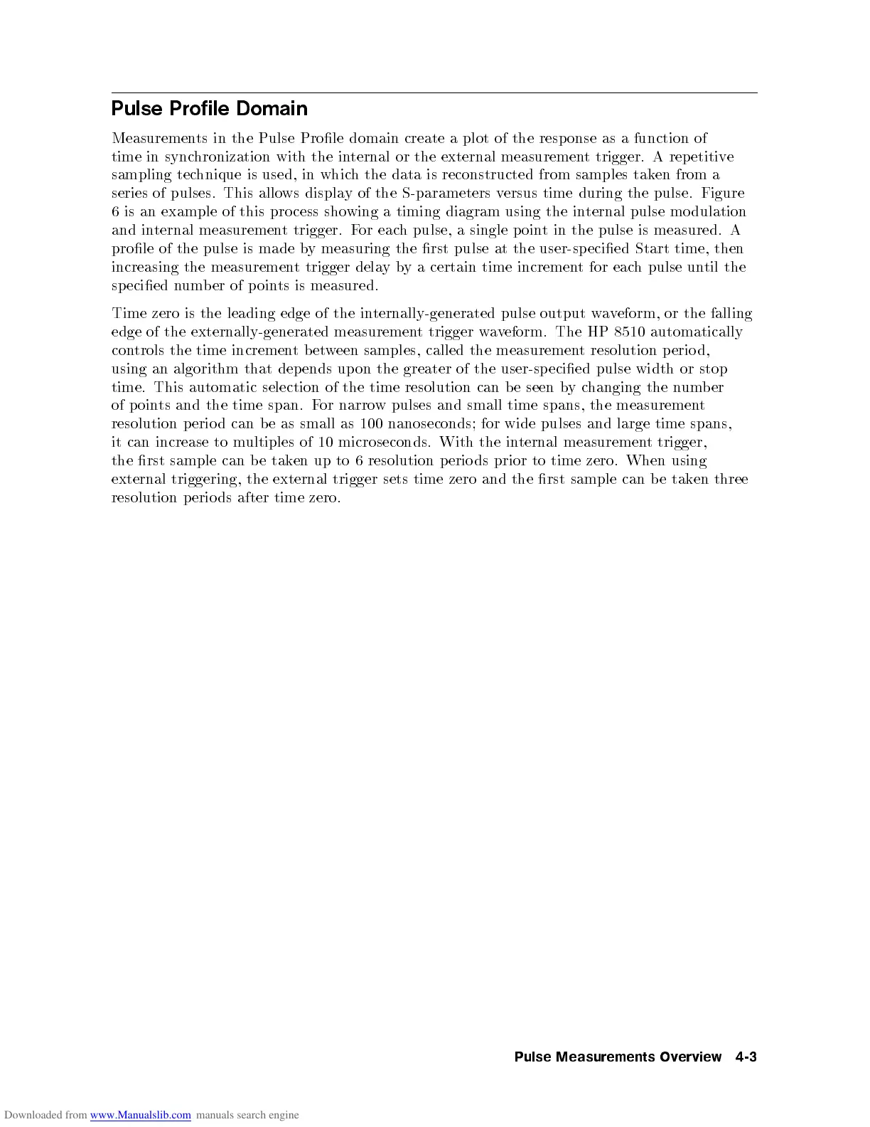
Measurements in the Pulse Prole domain create a plot of the response as a function of
time in synchronization with the internal or the external measurement trigger. A repetitive
sampling technique is used, in which the data is reconstructed from samples taken from a
series of pulses. This allows display of the S-parameters versus time during the pulse. Figure
6 is an example of this pro cess showing a timing diagram using the internal pulse mo dulation
and internal measurement trigger. For each pulse, a single p oint in the pulse is measured. A
prole of the pulse is made by measuring the rst pulse at the user-sp ecied Start time, then
increasing the measurement trigger delayby a certain time increment for each pulse until the
specied number of points is measured.
Time zero is the leading edge of the internally-generated pulse output waveform, or the falling
edge of the externally-generated measurement trigger waveform. The HP 8510 automatically
controls the time incrementbetween samples, called the measurement resolution p erio d,
using an algorithm that depends upon the greater of the user-sp ecied pulse width or stop
time. This automatic selection of the time resolution can be seen bychanging the number
of p oints and the time span. For narrow pulses and small time spans, the measurement
resolution
p
erio
d
can
b
e
as
small
as
100
nanoseconds;
for
wide
pulses
and
large
time
spans,
it
can
increase to
multiples
of 10
microseconds. With
the
in
ternal
measuremen
t
trigger,
the
rst
sample
can b
etak
en up
to 6
resolution
p
erio
ds
prior
to
time
zero.
When
using
external triggering,
the
external
trigger
sets
time
zero
and
the
rst
sample
can
b
e
tak
en
three
resolution
p
erio
ds
after
time
zero.
Pulse
Measurements
Ov
erview
4-3
 Loading...


