This o ccurs b ecause when the pulse is O, the network analyzer is measuring the ratio of
noise to noise, and since the noise is approximately equal in the reference and test signal
paths, the result is near 0 dB with respect to the On p erio d of the pulse. Also, in this
measurement, some large spikes may b e seen in the noisy part of the trace. If the noise in the
reference channel instantaneously go es to a very small value, the ratio will increase to a very
large value.
Note
In the Pulse Prole domain:
Without averaging, pulse width and duty cycle settings resulting in less than
about 3 milliseconds PRP will not change the actual system PRP.
With averaging, pulse width and duty cycle settings resulting in less than
about 1 millisecond PRP will not change the actual system PRP.
Also, the PRP and duty cycle can vary during the sweep. To learn more about
control of these values, refer to the General Timing Information chapter.
Frequency Domain Check
1.
Press
4
DOMAIN
5
N
N
N
N
N
N
NN
NN
NN
NN
N
N
N
N
N
N
N
N
N
N
N
N
N
N
N
FREQUENCY
.
2.
If
the
W
annotation do
es not
app
ear,
press
4
SYSTEM
5
N
N
N
N
N
N
N
N
N
N
N
N
N
N
MORE
N
N
N
N
N
N
N
N
N
N
N
N
N
N
N
N
NN
NN
N
N
N
N
N
N
N
N
N
N
N
N
N
N
N
N
N
N
PULSE
CONFIG
N
N
N
N
N
N
N
N
N
N
N
N
N
N
N
N
N
N
N
N
N
N
NN
NN
N
N
N
N
N
N
N
N
N
N
N
N
N
N
N
N
N
N
N
N
N
NN
NN
N
N
DETECTOR:
WIDE
BW
.
3.
Press
4
MARKER
5
,
then
mo
v
e
the
mark
er to
v
arious
p
oin
ts
on
the
trace.
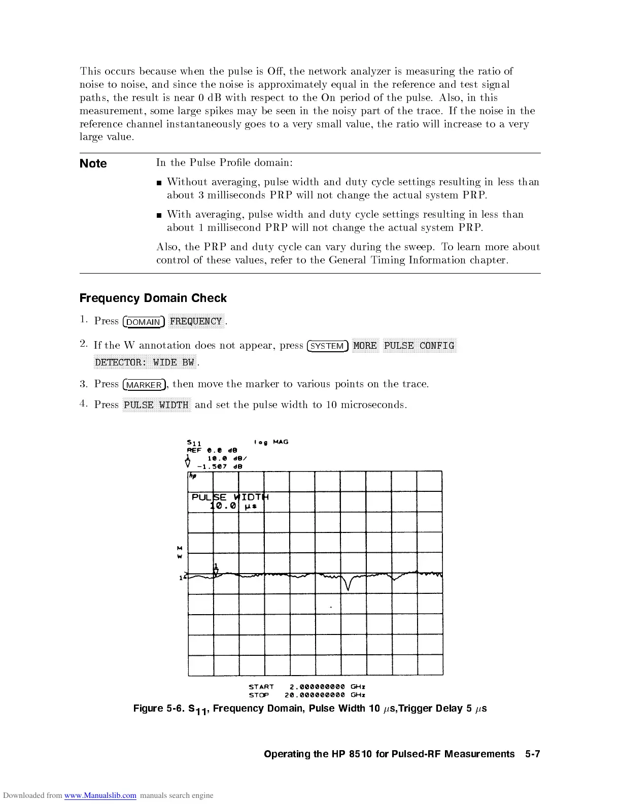
4.
Press
N
N
N
N
N
N
N
N
N
N
N
N
N
N
N
N
NN
N
N
N
N
N
N
N
N
N
N
N
N
N
N
N
N
N
PULSE
WIDTH
and
set the
pulse
width
to
10
microseconds.
Figure
5-6.
S
11
,
Frequency
Domain,
Pulse
Width
10
s,Trigger
Dela
y
5
s
Operating
the
HP
8510
for
Pulsed-RF
Measurements
5-7
 Loading...


