If you are viewing this with an oscilloscop e, notice how the measurement cycle time varies
according to the pulse prole stop time. If the stop time is greater than the pulse width, the
measurement cycle time will extend past the end of the pulse depending upon the time value
of the data point b eing measured. Dep ending upon the pulse width, this can result in a lower
percent duty cycle toward the end of the time span.
External Trigger and Stop Sweep Signals
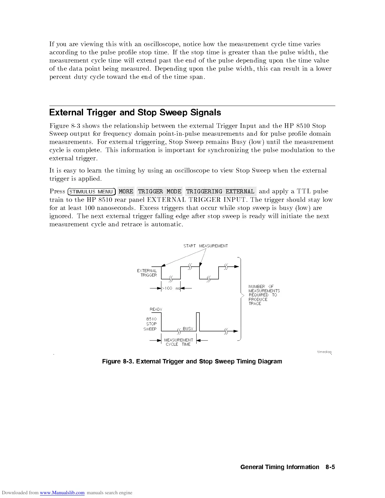
Figure 8-3 shows the relationship b etween the external Trigger Input and the HP 8510 Stop
Sweep output for frequency domain point-in-pulse measurements and for pulse prole domain
measurements. For external triggering, Stop Sweep remains Busy (low) until the measurement
cycle is complete. This information is imp ortant for synchronizing the pulse mo dulation to the
external trigger.
It is easy to learn the timing by using an oscilloscop e to view Stop Sweep when the external
trigger is applied.
Press
4
STIMULUS
MENU
5
NNNNNNNNNNNNNN
MORE
NNNNNNNNNNNNNNNNNNNNNNNNNNNNNNNNNNNNNN
TRIGGER
MODE
NNNNNNNNNNNNNNNNNNNNNNNNNNNNNNNNNNNNNNNNNNNNNNNNNNNNNNNNNNN
TRIGGERING
EXTERNAL
and
apply a
TTL pulse
train
to
the
HP 8510
rear panel
EXTERNAL TRIGGER
INPUT. The
trigger
should
sta
y
lo
w
for at
least
100
nanoseconds.
Excess
triggers
that
o
ccur
while
stop
sw
eep
is
busy
(lo
w)
are
ignored.
The
next
external
trigger
falling
edge
after
stop
sw
eep
is
ready
will
initiate
the
next
measuremen
t
cycle
and
retrace
is
automatic.
Figure
8-3.
External
Trigger and
Stop
Sw
eep
Timing
Diagram
General
Timing
Information
8-5
 Loading...


