Pulse Repetition Period and Duty Cycle Considerations
From this information it can be seen that the pulse repetition perio d and thus the duty cycle
of the pulsed-RF signal applied to the DUT can vary dep ending up on the instrument state.
For measurements in which the PRP or duty cycle is not imp ortant, simply set the pulse
width and the duty cycle controls to an appropriate value and make the measurement. The
specied duty cycle limit will not be exceeded, but the actual duty cycle maybe lessthan
expected.
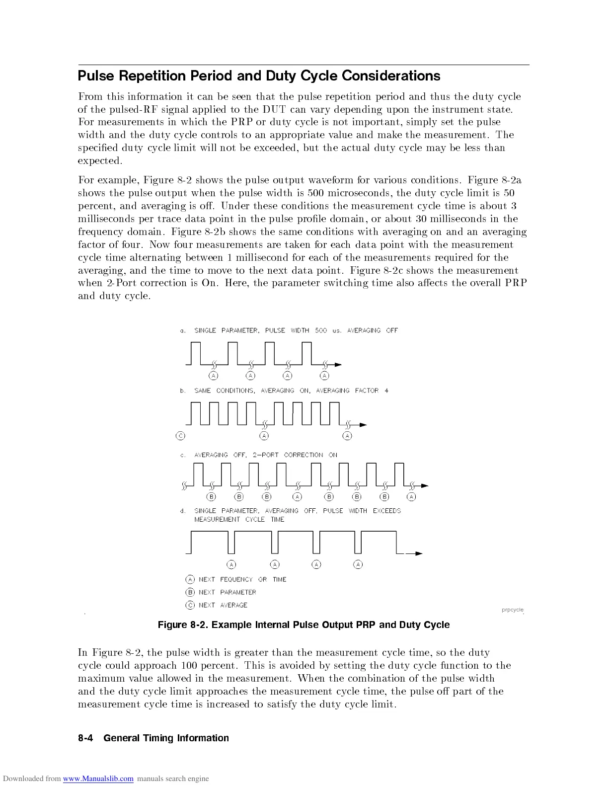
For example, Figure 8-2 shows the pulse output waveform for various conditions. Figure 8-2a
shows the pulse output when the pulse width is 500 microseconds, the duty cycle limit is 50
percent, and averaging is o. Under these conditions the measurement cycle time is ab out 3
milliseconds p er trace data point in the pulse prole domain, or ab out 30 milliseconds in the
frequency domain. Figure 8-2 b shows the same conditions with averaging on and an averaging
factor of four. Now four measurements are taken for each data p oint with the measurement
cycle time alternating between 1 millisecond for each of the measurements required for the
averaging, and the time to move to the next data point. Figure 8-2c shows the measurement
when 2-Port correction is On. Here, the parameter switching time also aects the overall PRP
and
dut
y
cycle.
Figure 8-2. Example Internal Pulse Output PRP and
Duty Cycle
In Figure 8-2 , the pulse width is greater than the measurement cycle time, so the duty
cycle could
approac
h
100
p
ercen
t.
This
is
a
v
oided
b
y
setting
the
dut
y
cycle
function
to
the
maxim
um
v
alue
allo
w
ed
in
the
measuremen
t.
When
the
com
bination
of
the
pulse
width
and
the
dut
y
cycle
limit
approac
hes
the
measuremen
t
cycle
time, the
pulse
o
part
of
the
measuremen
t
cycle
time
is
increased to
satisfy
the
dut
y
cycle
limit.
8-4
General
Timing
Information
 Loading...


