Example High Power Measurements
The best pro cedure for setting signal levels in the test set b egins with estimating the input
and output p ower levels of the device under test. When the test set is congured to handle
these levels, the op erating device is connected and the p ower estimates are veried by
measuring the user parameters. If the estimates were inaccurate, the test set conguration
is changed so that p ower levels at all p oints in the system are within limits. When this is
accomplished, the device is removed, measurement calibration is p erformed, then the device is
installed and its S-parameters are measured. Following are two examples of measurements on
high p ower devices.
Measure a 30 dB Amplifier
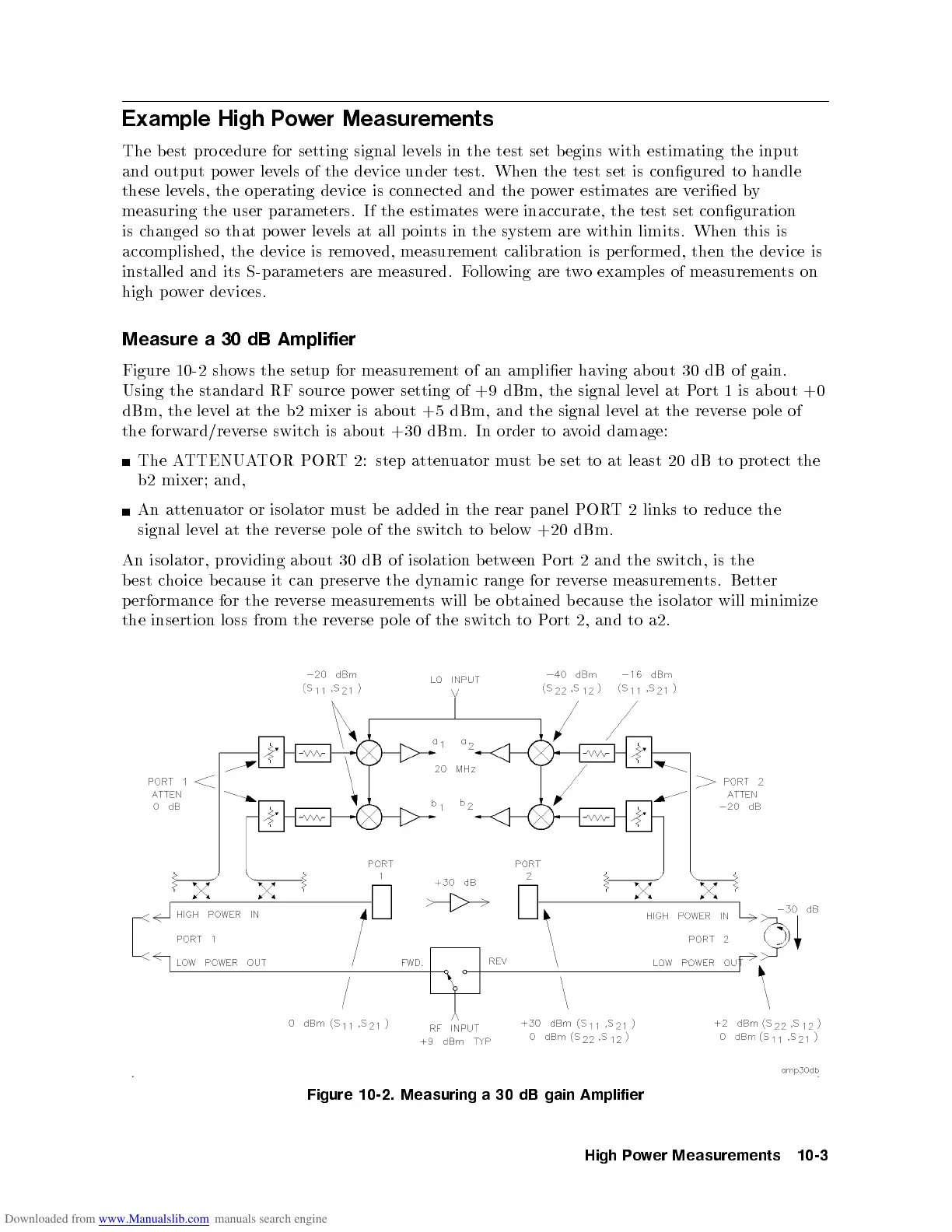
Figure 10-2 shows the setup for measurement of an amplier having ab out 30 dB of gain.
Using the standard RF source p ower setting of +9 dBm, the signal level at Port 1 is ab out +0
dBm, the level at the b2 mixer is about +5 dBm, and the signal level at the reverse p ole of
the forward/reverse switch is ab out +30 dBm. In order to avoid damage:
The ATTENUATOR PORT 2: step attenuator must b e set to at least 20 dB to protect the
b2
mixer;
and,
An
atten
uator
or
isolator
m
ust
b
e
added in
the rear
panel POR
T2
links
to
reduce
the
signal
lev
el
at
the rev
erse p
ole
of
the
switc
h
to
b
elo
w
+20
dBm.
An
isolator,
pro
viding
ab
out
30 dB
of isolation
b
et
w
een
P
ort
2
and
the
switc
h,
is
the
b
est
c
hoice
b
ecause
it
can
preserv
ethe
dynamic
range
for
rev
erse
measuremen
ts.
Better
p
erformance
for the
rev
erse
measuremen
ts
will
b
e
obtained
b
ecause
the
isolator
will
minimize
the
insertion
loss
from
the
rev
erse
p
ole
of
the
switc
h
to
P
ort
2,
and
to
a2.
Figure
10-2.
Measuring
a
30
dB
gain
Amplifier
High
P
o
w
er
Measurements
10-3
 Loading...


