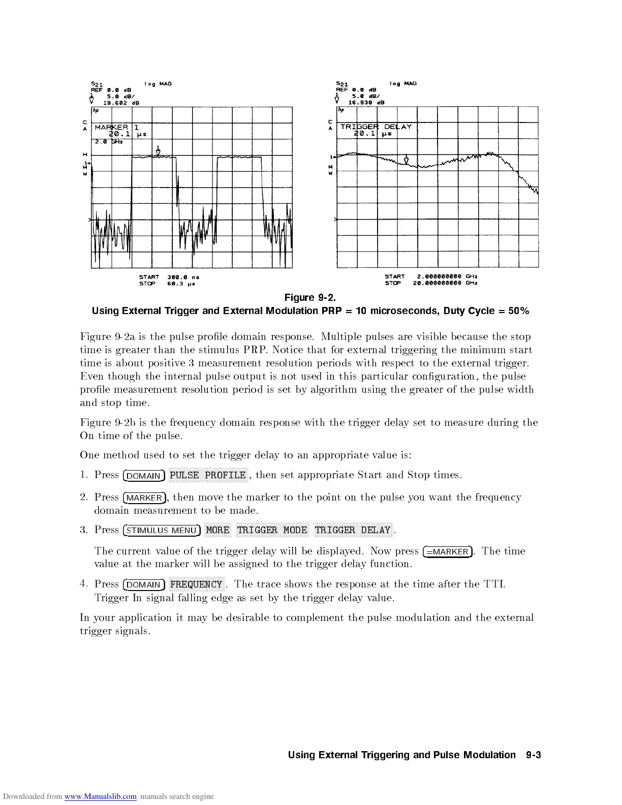
Figure 9-2.
Using
External
Trigger
and External
Modulation PRP
=10
microseconds, Duty
Cycle
=
50%
Figure
9-2a
is
the
pulse
prole
domain
resp
onse.
Multiple
pulses
are
visible
b
ecause
the
stop
time
is
greater
than
the
stim
ulus
PRP
.
Notice
that
for
external
triggering
the
minim
um
start
time
is
ab
out
p
ositiv
e
3
measuremen
t
resolution p
erio ds
with
resp
ect
to
the
external
trigger.
Ev
en
though
the
in
ternal pulse
output
is
not
used
in
this
particular
conguration,
the
pulse
prole
measuremen
t
resolution
p
erio
d
is
set
b
y
algorithm
using
the
greater
of
the
pulse
width
and
stop
time.
Figure
9-2
b
is
the
frequency
domain
resp
onse
with
the
trigger
dela
y
set
to
measure
during
the
On
time
of
the
pulse.
One
metho
d
used
to
set
the
trigger
dela
y
to
an
appropriate
value
is:
1.
Press
4
DOMAIN
5
N
NN
NN
NN
NN
N
N
N
N
N
N
N
N
N
N
N
N
N
N
N
N
N
NN
NN
NN
NN
N
N
N
N
N
N
N
PULSE
PROFILE
,
then
set
appropriate
Start
and
Stop
times.
2.
Press
4
MARKER
5
, then move the marker to the p oint on the pulse you want the frequency
domain measurement to b e made.
3. Press
4
STIMULUS MENU
5
NNNNNNNNNNNNNN
MORE
NNNNNNNNNNNNNNNNNNNNNNNNNNNNNNNNNNNNNN
TRIGGER MODE
NNNNNNNNNNNNNNNNNNNNNNNNNNNNNNNNNNNNNNNNN
TRIGGER DELAY
.
The currentvalue of the trigger delay will be displayed. Now press
4
=MARKER
5
. The time
v
alue
at
the
marker
will
b
e
assigned
to
the
trigger
dela
y
function.
4.
Press
4
DOMAIN
5
N
N
N
N
N
N
N
N
N
N
N
NN
N
N
N
N
N
N
N
N
N
N
NN
N
N
N
N
FREQUENCY
.
The
trace
sho
ws
the
resp
onse
at
the
time after
the
TTL
Trigger In signal falling edge as set b
y the trigger dela
yv
alue.
In y
our application
it ma
y b e desirable to complemen
t the pulse mo dulation and the external
trigger signals.
Using
External
Triggering
and
Pulse
Modulation
9-3
 Loading...


