13
Rack-mounting the A5120 SI switch in a 19-inch
rack
Figure 10 shows the general procedure for installing an A5120 SI switch in a 19-inch rack.
Figure 10 Install an A5120 SI switch in a 19-inch rack
Choose proper installation
positions for mounting brackets
Install the mounting
brackets to the left and
right sides of the switch
Mount the
switch to a rack
Mounting brackets and mounting positions
Table 8 Mounting brackets for the A5120 SI switches
A5120-16G SI
A5120-24G SI
See callout A in Figure 11.
Front mounting (see Figure 12)
Rear mounting (see Figure 13)
A5120-24G-PoE+ SI
A5120-24G-PPoE+ SI
See callout B in Figure 11.
Front mounting (see Figure 14)
Mid-mounting (see Figure 15)
Rear mounting (see Figure 16)
See callout B in Figure 11.
Front mounting (see Figure 14)
Rear mounting (see Figure 16)
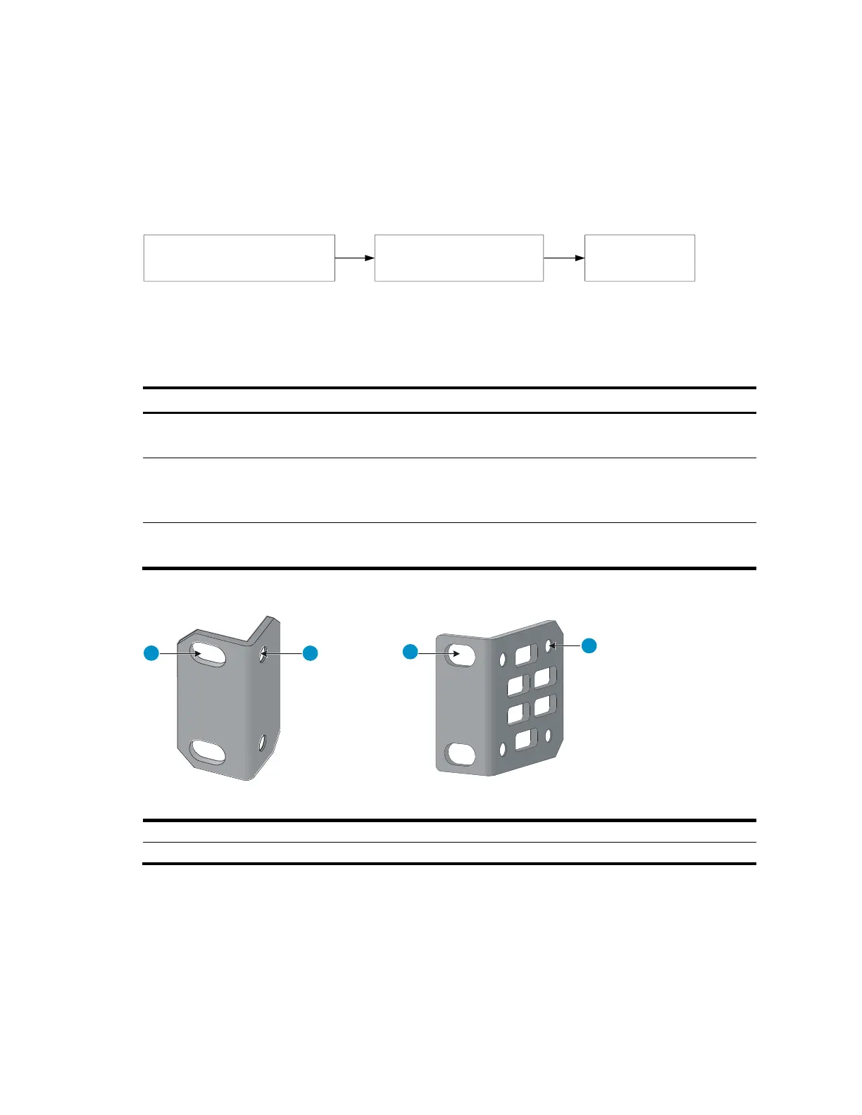
Figure 11 Mounting brackets
(1) Holes for attaching to a rack (by using M6 screws)
(2) Holes for attaching to the switch chassis
Attaching the mounting brackets to the switch chassis
To attach the mounting brackets to the switch chassis:
1. Identify the correct mounting position (see Table 8).
2. Align the round holes in one bracket with the holes in the mounting position.
3. Use screws to fasten the mounting bracket to the chassis.
 Loading...


