24
Figure 27 Connect the RPS cable to the +12 VDC RPS receptacle
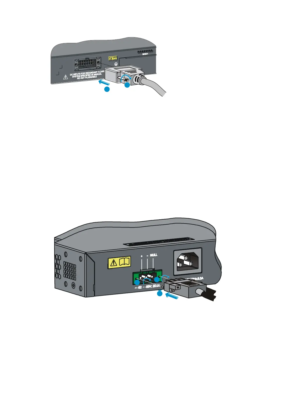
Connecting the switch to a –52 to –55 VDC output RPS
This section applies to the A5120-24G-PoE+ EI (2 slots), A5120-24G-PoE+ EI TAA (2 slots), A5120-48G-
PoE+ EI (2 slots), A5120-48G-PoE+ EI TAA (2 slots) and A5120-24G-PoE+ SI switches.
To connect these switches to the RPS that provides –52 to –55 VDC output:
1. The RPS cable provided with the switch has a directional plug that fits the switch's RPS receptacle.
Orient the plug to the RPS receptacle, and insert the plug as shown in Figure 28.
Do not use excessive force. The RPS receptacle is directional. If you cannot insert the plug, re-orient
the plug so it fits.
2. Tighten the screws on the plug with a flat-blade screwdriver.
3. Connect the other end of the power cord to the RPS.
4. Verify that the RPS is supplying power and that the RPS status LED is ON.
Figure 28 Connect the RPS cable to the –52 to –55 RPS receptacle
 Loading...


