74
Seven-segment LED
The seven-segment LED, together with the system status LED, shows detailed system operating information,
as described in Table 22.
The seven-segment LED can also show the total PoE output power as a percentage of the maximum PoE
output power that a PoE switch can supply (see Table 23). The PoE switches include:
A5120-24G-PoE+ EI (2 slots)
A5120-24G-PoE+ EI TAA (2 slots)
A5120-48G-PoE+ EI (2 slots)
A5120-48G-PoE+ EI TAA (2 slots)
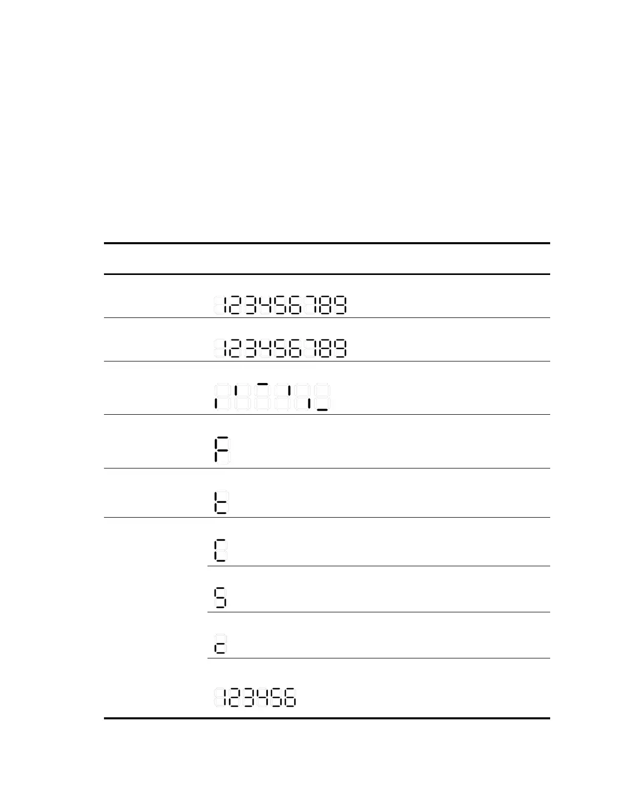
Table 22 Seven-segment LED description (I)
System status LED
(PWR) status
Seven-segment LED (Unit) status
The LED displays numbers one by one.
POST is running, and the LED
displays the ongoing test item ID.
The LED displays flashing numbers.
POST has failed, and the LED flashes
the ID of the failed test item.
A bar rotates clockwise around the LED.
The LED displays a flashing F character.
The switch is experiencing a fan
failure.
The LED displays a flashing t character.
The switch is in an overheated
condition.
The LED displays a capital C character.
The switch is the command switch in
a cluster.
The LED displays an S character.
The switch is a member switch in a
cluster.
The LED displays a lowercase c character.
The switch is a candidate switch for
a cluster.
The LED displays a number.
The member ID of the switch in an
IRF fabric.
The A5120-24G EI and A5120-
48G EI switches do not support IRF.
 Loading...


