22
Connecting the power cord
WARNING!
Make sure that the grounding cable has been properly connected before powering on the switch.
Use Table 9 to identify the power cord connection procedures for your switch.
Table 9 Power cord connection methods at a glance
A5120-16G SI
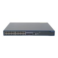
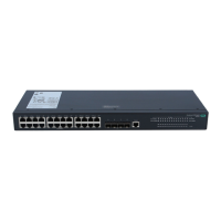
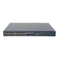
A5120-24G SI
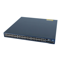
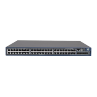
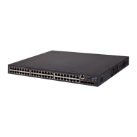
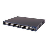
A5120-48G SI
A5120-24G-PPoE+ SI
Connecting the AC power cord
AC-input:
Connecting the AC power cord
RPS input:
Connecting the switch to a –52 to –55 VDC output RPS
A5120-24G EI (2 slots)
A5120-24G EI TAA (2 slots)
A5120-48G EI (2 slots)
A5120-48G EI TAA (2 slots)
A5120-24G EI
A5120-48G EI
AC-input:
Connecting the AC power cord
RPS input:
Connecting the switch to a +12 VDC output RPS
A5120-24G-PoE+ EI (2 slots)
A5120-24G-PoE+ EI TAA (2 slots)
A5120-48G-PoE+ EI (2 slots)
A5120-48G-PoE+ EI TAA (2 slots)
AC-input:
Connecting the AC power cord
RPS input:
Connecting the switch to a –52 to –55 VDC output RPS
Connecting the AC power cord
To connect the AC power cord:
1. Wear an ESD-preventive wrist strap and make sure it makes good skin contact and is properly
grounded.
2. Connect one end of the AC power cord to the AC-input power receptacle on the switch. For
examples, see Figure 24 (A5120-48G EI) and Figure 25 (A5120-24G SI).
3. Connect the other end of the AC power cord to the AC power outlet.
 Loading...

