EasyManua.ls Logo

HP A5800 Series User Manual

HP A5800 Series
146 pages
To Next Page IconTo Next Page
To Previous Page IconTo Previous Page
Page #123 background imageLoading...
Page #123 background image
117
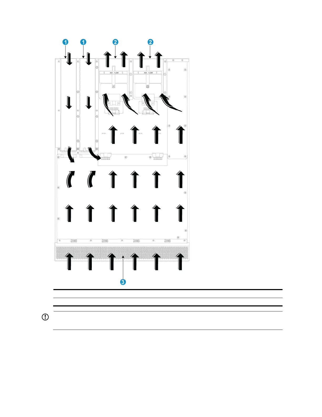
Figure 99 Airflow through the chassis (with LSWM1FANSCB fan trays)
(1) Power supply air vents
(2) Fan tray air vents
(3) Network port-side air vents
IMPORTANT:
The chassis and the power supplies use separate air aisles. Make sure that both aisles are not blocked.
A5800-24G/A5800-24G TAA
Figure 100 shows the airflow design for the A5800-24G and A5800-24G TAA switches. Cool air flows in
from the left side of the chassis, circulates through the chassis and the interface card, and exhausts out the
right side of the chassis.

Table of Contents

Question and Answer IconNeed help?

Do you have a question about the HP A5800 Series and is the answer not in the manual?

HP A5800 Series Specifications

General IconGeneral
ModelHP A5800 Series
ManagementCLI, SNMP, Web
Dimensions4.36 x 44 x 48 cm (1.72 x 17.32 x 18.9 in)
MAC Address Table Size32K entries
VLANs Supported4094
Routing ProtocolsOSPF, BGP, RIP, IS-IS
Operating Temperature32°F to 113°F (0°C to 45°C)
Operating Humidity10% to 90% (noncondensing)

Related product manuals