EasyManua.ls Logo

HP A5800 Series User Manual

HP A5800 Series
146 pages
To Next Page IconTo Next Page
To Previous Page IconTo Previous Page
Page #89 background imageLoading...
Page #89 background image
83
A5800-24G-SFP (1 slot)/A5800-24G-SFP TAA (1
slot) panel views
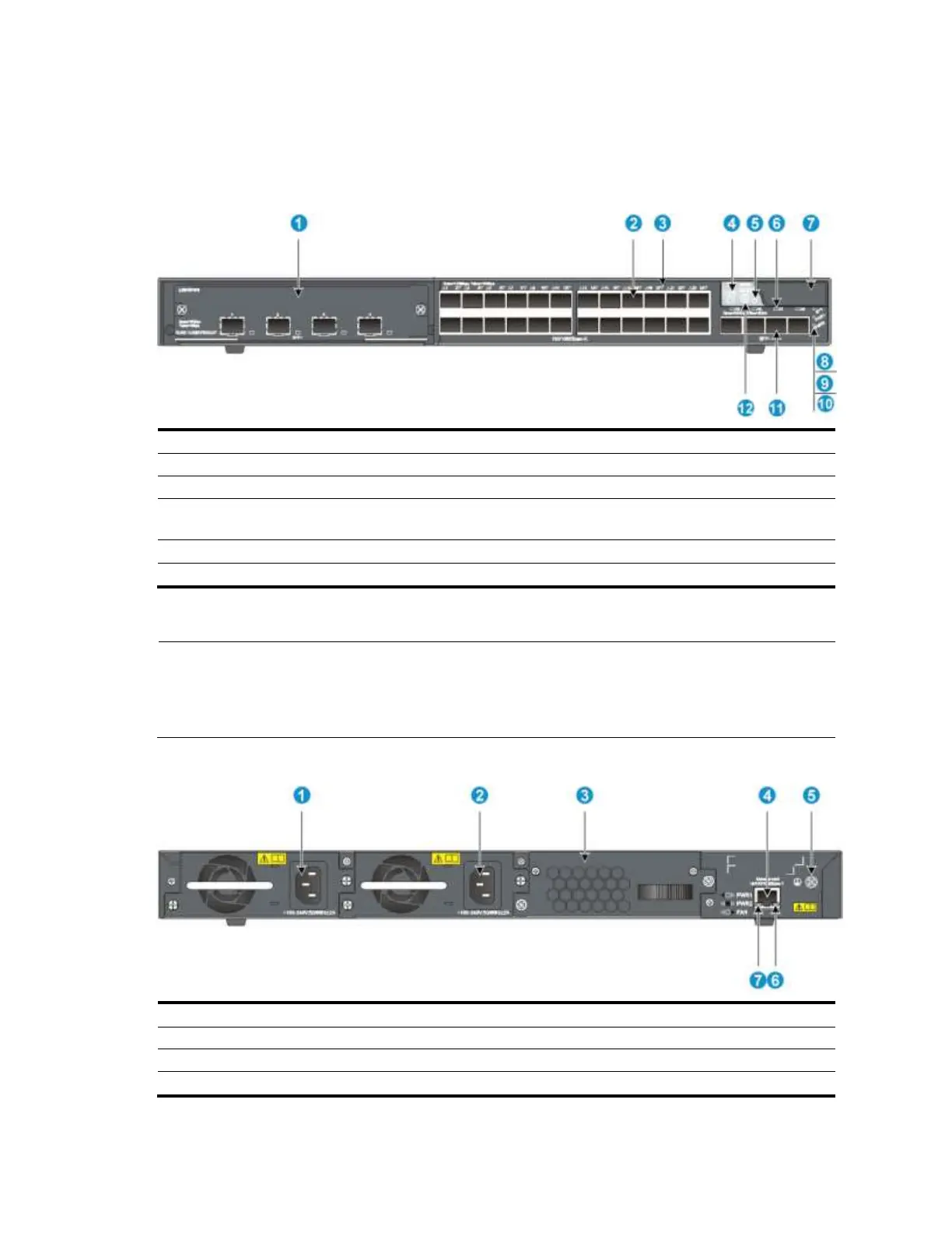
Figure 84 Front panel
(1) Interface card slot
(2) 100/1000Base-X SFP port
(3) 100/1000Base-X SFP port LED
(4) Seven-segment LED
(5) Port mode LED
(6) SFP+ port LED
(7) Logo plate (A console port and a USB port are
under this logo plate)
(8) System status LED (SYS)
(9) Power supply 1 status LED (PWR1)
(10) Power supply 2 status LED (PWR2)
(11) SFP+ port
(12) Port LED mode switching button
To use the console port and USB port, open the logo plate, as shown in Figure 72 and Figure 73.
NOTE:
The A5800-24G-SFP (1 slot) and A5800-24G-SFP TAA (1 slot) switches come with the expansion
interface card slot covered by a filler panel. In this figure, an LSW1SP4P0 interface card is installed in
the slot.
Figure 85 Rear panel
(1) Power supply slot 1
(2) Power supply slot 2
(3) Hot swappable fan tray
(4) Management Ethernet port
(5) Grounding screw
(6) ACT LED for the management Ethernet port
(7) LINK LED for the management Ethernet port

Table of Contents

Question and Answer IconNeed help?

Do you have a question about the HP A5800 Series and is the answer not in the manual?

HP A5800 Series Specifications

General IconGeneral
ModelHP A5800 Series
ManagementCLI, SNMP, Web
Dimensions4.36 x 44 x 48 cm (1.72 x 17.32 x 18.9 in)
MAC Address Table Size32K entries
VLANs Supported4094
Routing ProtocolsOSPF, BGP, RIP, IS-IS
Operating Temperature32°F to 113°F (0°C to 45°C)
Operating Humidity10% to 90% (noncondensing)

Related product manuals