Installing and Removing an RPE
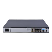
Interior Structure of an RPE
Interior structure of the RPE
(1) Memory module
(3) CPU heatsink
(5) Release latch
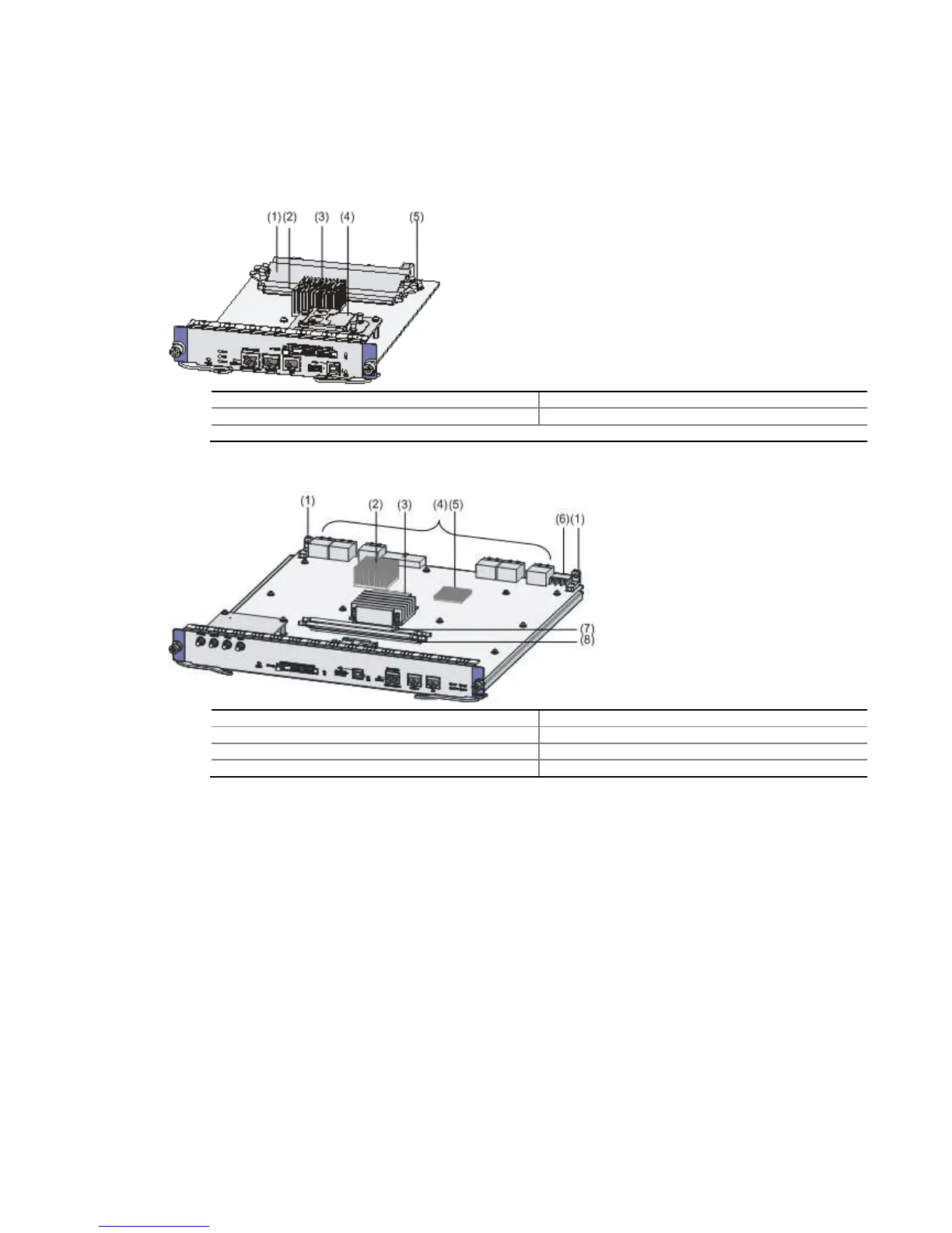
Figure 4-9
Interior structure of the RSE
(1) Positioning holes
(3) CPU heatsink
(5) Bridge heatsink 2
(7) Memory module
Installing an RPE-X1
Step1
Face the front panel of the router.
Locate the slot where you will install the RPE
Step3 Install a chassis accessory
Installing and Removing an RPE
Interior Structure of an RPE
Interior structure of the RPE
Interior structure of the RSE
-X1
(2) Bridge heatsink 1
(4) Bus connectors
(6) Power connector
(8) Release latch
Face the front panel of the router.
Locate the slot where you will install the RPE
X1 (Slot 4 or Slot 5; the figures below illustrate
X1 (Slot 4 or Slot 5; the figures below illustrate
 Loading...