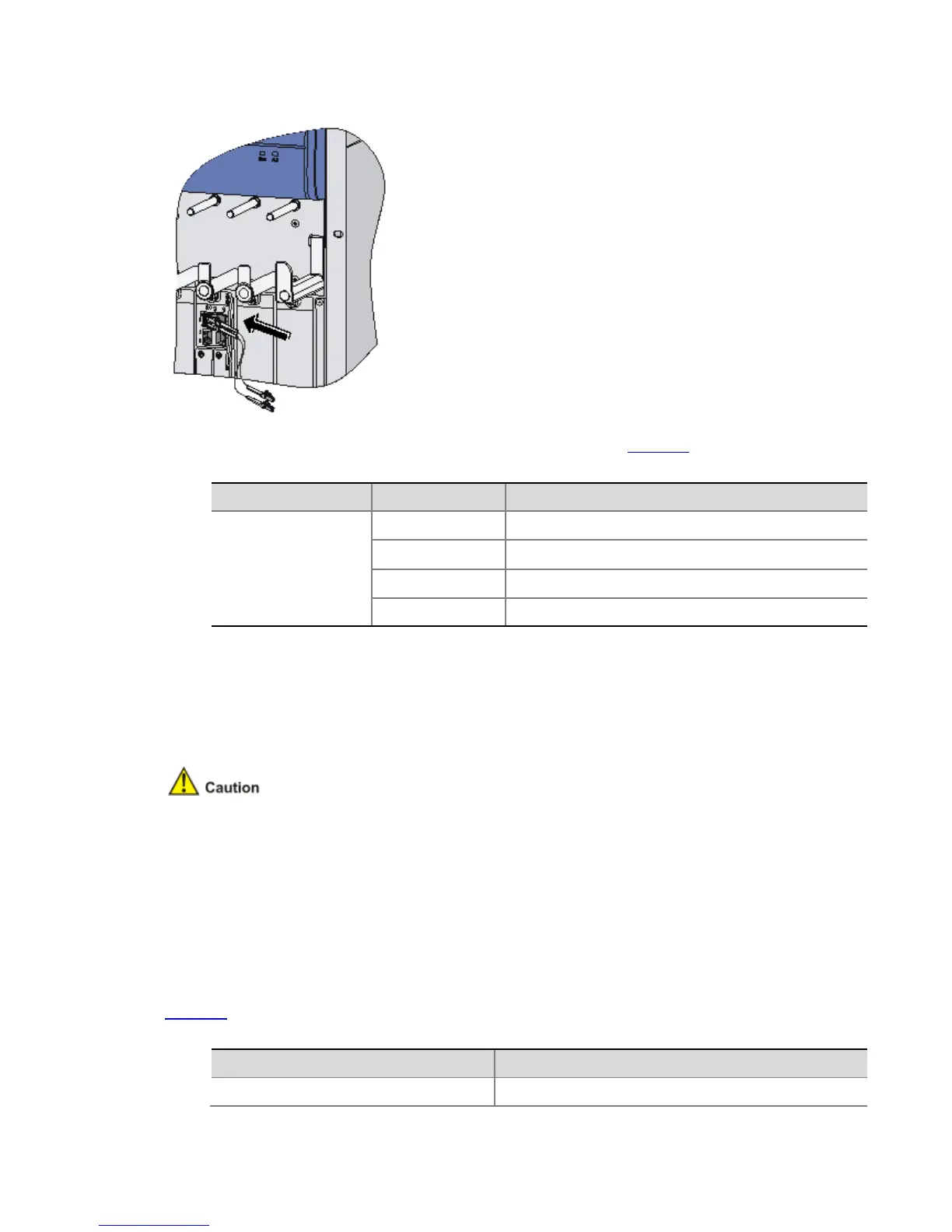
Figure 4-41 Plug fiber connectors
Step4 View the SFP LED after power-on. For the status of the SFP LED, see Table 4-3.
Table 4-3 Status of the SFP LED
LED Color Status
SFP0/SFP1
(yellow/green)
Off No optical fiber link is present.
Solid green An optical fiber link is present.
Blinking green Data is being transmitted or received at 1000 Mbps.
Solid yellow The optical transceiver is not recognizable.
Note that:
Avoid excessively bending optical fiber cables, with the curvature radius less than 10 cm (3.9
in.).
Ensure that the Tx and Rx ports of the SFP transceiver module are connected correctly.
Keep the end-faces of optical fiber cables clean.
Never stare into an open optical Ethernet interface, because invisible rays may be emitted from
the optical Ethernet interface.
Cover the dust cover if no optical fiber connector is connected to the optical Ethernet interface.
Connecting the Power Cables
Power Supply Interface and PGND Terminal
You can use AC power modules for AC power input or DC power modules for DC power input
for the router. For the specifications for the power supply interface and PGND terminal, see
Table 4-4.
Table 4-4 Power supply interface and PGND terminal of the router
Item Description
AC power socket ( AC-powered) Provides 100 VAC to 240 VAC
 Loading...