7
FCoE frames
To transmit an FC frame over Ethernet, FCoE encapsulates the FC frame in an FCoE frame by adding an
Ethernet frame header to the FC frame.
An FCoE frame uses Ethernet II encapsulation, which has the following fields in the Ethernet header:
• EtherType 0x8906.
• Destination MAC address/source MAC address—The definitions of this field are different for
switches and nodes.
{ For a switch, it is the FCoE MAC address of the switch (which can be displayed by using the
display fcoe command).
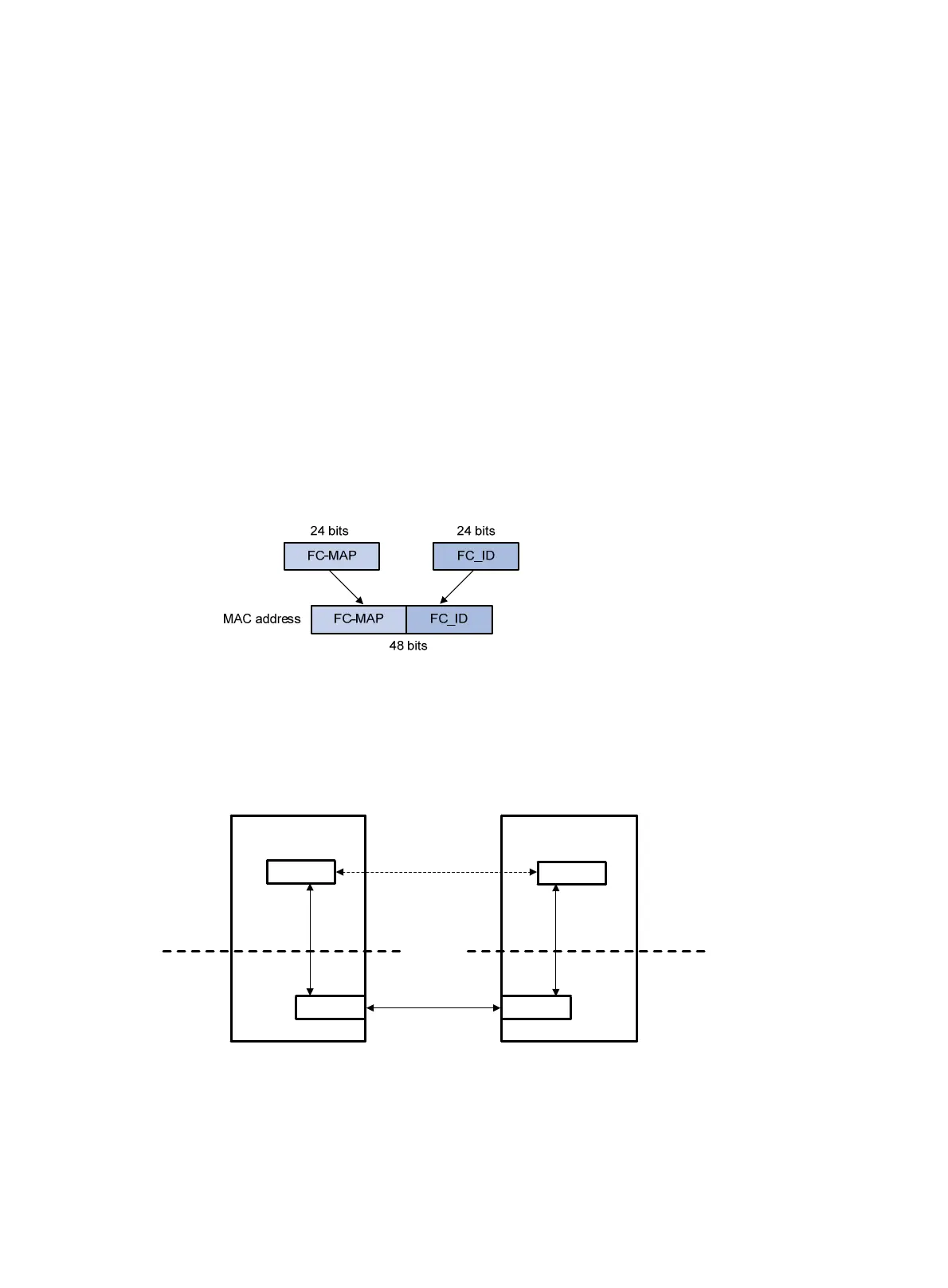
{ For a node, it is the fabric provided MAC address (FPMA) of the node. As shown in Figure 7, an
FPMA is composed of the following elements:
− The FC-MAP as the 24 most significant bits.
− The FC ID of the VN interface as the 24 least significant bits.
The FC-MAP takes the value of the switch FC-MAP, 0x0EFC00 by default and configurable by
using the fcoe fcmap command.
Figure 7 FPMA composition
How FCoE works
This section describes how FCoE works on the FCF switch (rather than the ENode).
Figure 8 Block diagrams of the ENode and the FCF switch
Procedure for receiving and sending FC frames over Ethernet
An FC frame is transmitted over Ethernet using the following workflow:
1. FIP establishes a virtual link between the VFC interface of the FCF switch and one of the following
interfaces:
Virtual link
ENode FCF
VN interface
VFC interface
FC layer
Ethernet
layer
Ethernet
interface
Ethernet
interface
FC layer
Ethernet
layer
 Loading...


