142
• Switch A and Switch B are uniformly managed, and the hardware resources and software
processing capabilities of the two switches are integrated. When one switch fails, the other switch
can quickly take over to avoid service interruption.
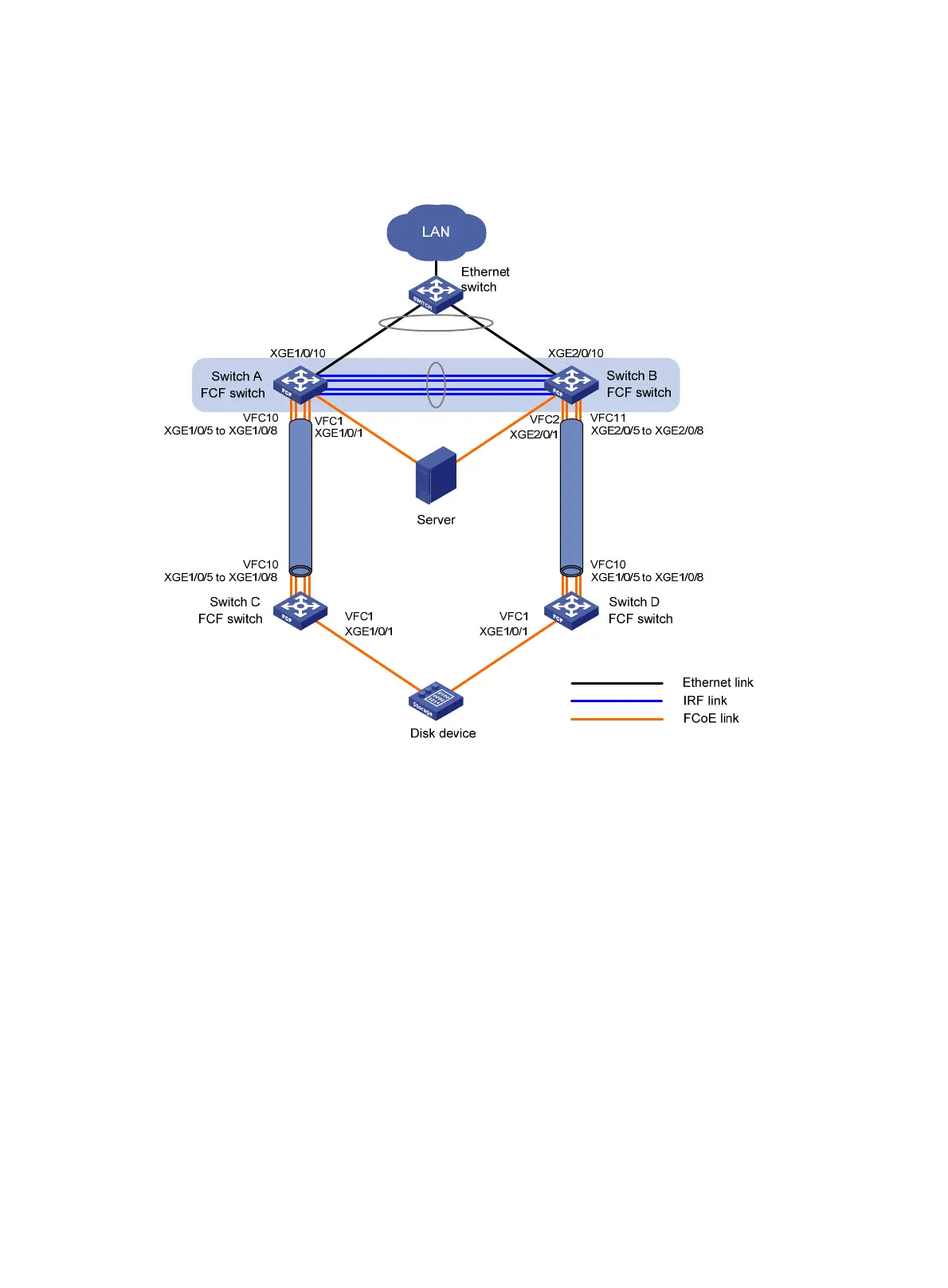
Figure 36 Network diagram
Requirements analysis
To meet the network requirements, perform the following tasks:
• To uniformly manage Switch A and Switch B and implement backup between them, configure
Switch A and Switch B to form an IRF fabric. The IRF fabric uses Switch A as the master device. The
IRF fabric operates at the access layer of the LAN and operates as the FCF switch of the SANs.
• Aggregate the four physical links connecting Switch A to Switch B into an IRF link, with ports
IRF-port 1/1 and IRF-port 2/2 at the two ends, respectively. Aggregate the links from the Ethernet
switch to Switch A and Switch B.
• To transmit the storage traffic over lossless Ethernet links in the SANs, HP recommends that you
perform the following tasks:
{ Configure DCBX, PFC in auto mode, and ETS on the Ethernet interfaces connecting the switches
to the server.
{ Configure DCBX and PFC in auto mode on the Ethernet interfaces connecting the switches to the
disk device.
{ Enable PFC by force on the Ethernet interfaces connecting switches.
Link aggregation 2
Link aggregation 1
 Loading...