1-8
Introducing the E3800 Switches
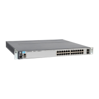
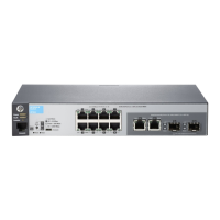
Fronts of the Switches
Out-of-Band Management (OOBM) Port
This RJ-45 port is used to connect a dedicated management network to the
switch.
Auxiliary (Aux) Port
An auxiliary port for processing a USB command file or downloading switch
software code. This port uses a USB Type A connector, but does not comply
with USB protocols and standards.
Switch and Port LEDs
■ Table 1-3 describes the switch and port LEDs and their operation for
standalone E3800 switches.
■ Table 1-4 describes the operation of the LEDs when the switches are
stacked. It includes descriptions of all stacking-related LEDs including
those for Module Status and Stacking Status.
Table 1-3. Standalone Switch and Port LED Behavior
Switch LEDs State Meaning
Power
(green)
On
Off
The switch is receiving power.
The switch is NOT receiving power.
Fault
(orange)
Off The normal state; indicates there are no fault conditions on the switch.
Blink
orange*
A fault has occurred on the switch, one of the switch ports, module in the rear of the
switch, or the fan. The Status LED for the component with the fault will blink
simultaneously.
On On briefly after the switch is powered on or reset, at the beginning of switch self test.
If this LED is on for a prolonged time, the switch has encountered a fatal hardware
failure, or has failed its self test. See chapter 4, “Troubleshooting” for more information.
Locator
(blue)
On
Blinking
Off
The Locator LED is used to help you identify a specific in your network equipment
installation. The LED can be set to be on solid or to blink, and for a specified number of
minutes (1-1440). The default is 30 minutes. Use the command “chassislocate” to
control this LED.
 Loading...