Peer dispersion: 34.30 ms
Reference time: 16:01:51.713 UTC Sep 19 2005 (C6D95F6F.B6872B02)
The output shows that Switch A has been synchronized to Switch C, and the clock stratum level of Switch
A is 3, while that of Switch C is 2.
# View the NTP session information of Switch A, which shows that an association has been set up
between Switch A and Switch C.
[SwitchA-Vlan-interface2] display ntp-service sessions
source reference stra reach poll now offset delay disper
**************************************************************************
[1234] 3.0.1.31 127.127.1.0 2 254 64 62 -16.0 32.0 16.6
note: 1 source(master),2 source(peer),3 selected,4 candidate,5 configured
Total associations : 1
Configuring NTP multicast mode
Network requirements
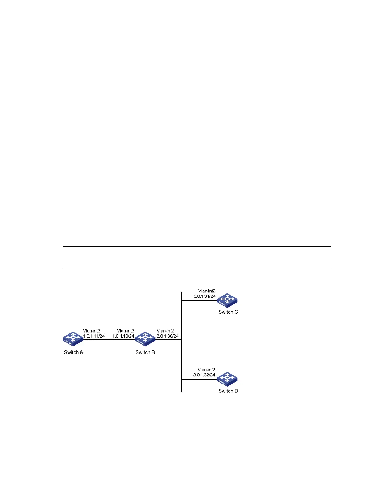
As shown in 0, Switch C functions as the NTP server for multiple devices on different network segments
and synchronizes the time among multiple devices as follows:
• Switch C’s local clock is to be used as a reference source, with the stratum level of 2.
• Switch C works in multicast server mode and sends out multicast messages from VLAN-interface 2.
• Switch A and Switch D work in multicast client mode and receive multicast messages through
VLAN-interface 3 and VLAN-interface 2 respectively.
NOTE:
In this example, Switch B must be a Layer 3 switch supporting multicast routing.
Figure 26 Network diagram for NTP multicast mode configuration
Configuration procedure
1. Set the IP address for each interface as shown in 0. (Details not shown)
2. Configure Switch C:
# Configure Switch C to work in multicast server mode and send multicast messages through
VLAN-interface 2.
66
 Loading...

