9 Power module slot 2
NOTE
Available power modules:
l 500 W AC Power Module
l 500 W DC Power Module
10 Power module slot 1
NOTE
Available power modules:
l 500 W AC Power Module
l 500 W DC Power Module
2.4.3 Indicator Description
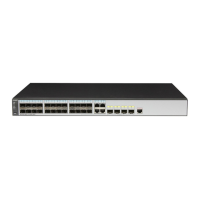
S6700-24-EI
NOTE
Symbols and meanings of indicators on the S6700-48-EI are the same as those on the S6700-24-EI.
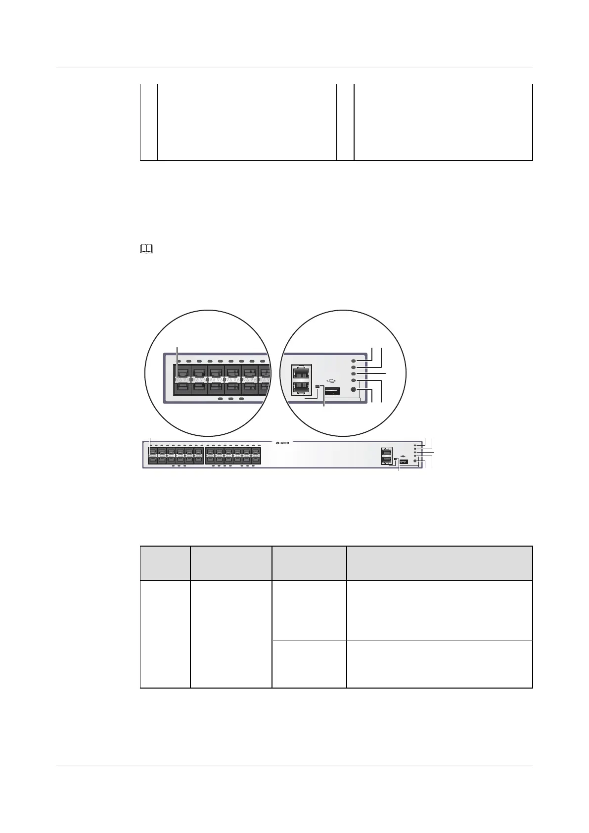
Figure 2-4 Indicators on the S6700-24-EI
2
1
11
12
13
14
23
24
Quidway S6700 Series
CONSOLE
ETH
GREEN=SPEED RED=STACK
LINK/ACT
PWR1
PWR2
SYS
MODE
2
1
11
1
Quidway S6700 Series
6
CONSOLE
ETH
GREEN=SPEED RED=STACK
LINK/ACT
PWR1
PWR2
SYS
MODE
12
3
54
7
Table 2-4 Description of indicators on the switch
Numbe
r
Indicator/
Button
Color Description
1 PWR1: power
supply indicator
- Off: No power module is available in
power module slot 1, or the switch has only
one power module but the power module
does not work normally.
Green Steady on: A power module is installed in
power module slot 1 and is working
normally.
S6700 Series Ethernet Switches
Hardware Description 2 Chassis
Issue 12 (2015-07-31) Huawei Proprietary and Confidential
Copyright © Huawei Technologies Co., Ltd.
15

 Loading...