b. Place the front end of the SAS controller in the retention bracket and align
the SAS riser card with the SAS riser-card connector on the system board.
c. Press down on the SAS riser card and the rear edge of the SAS controller
until the SAS riser card is firmly seated and the SAS controller card
retention latch clicks into place.
One or two pins (depending on the size of the card) clicks into the corner
holes of the SAS controller card when the controller card is correctly seated.
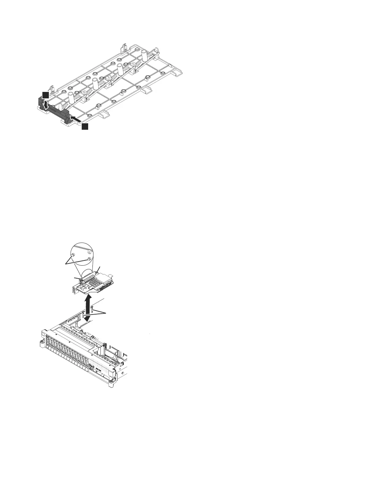
3. To install the SAS riser-card and controller assembly for a tape-enabled server
model, complete the following steps.
Figure 27 shows the SAS riser card in the tape-enabled server model.
a. Align the pins on the backside of the riser with the slots on the side of the
chassis.
b. Align the SAS riser card of the SAS controller assembly with the SAS
riser-card connector on the system board.
1
2
sonas206
Figure 26. Sliding the controller retention bracket inward and pressing the release tab
SAS riser card
Release latch
Pins
Slots
sonas209
Figure 27. SAS riser-card assembly on tape-enabled server model
116 Storwize V7000 Unified: Problem Determination Guide Version
 Loading...


