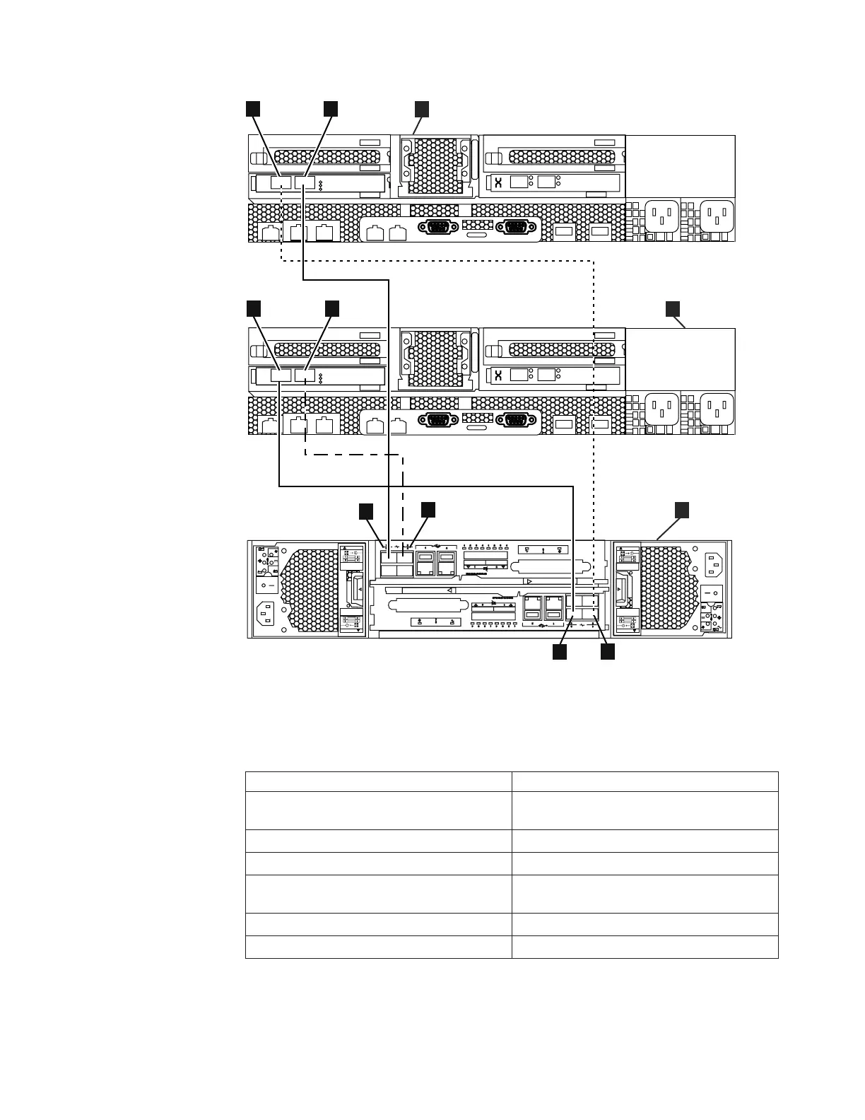
Table 10. How to connect Fibre Channel cables from file modules to the control enclosure.
Refer to the previous graphic.
File module Control enclosure
A File module 1 (usually lower in the
rack)
C Control enclosure
2 Fibre Channel slot 2, port 1 5 Upper canister Fibre Channel port 1
1 Fibre Channel slot 2, port 2 8 Lower canister Fibre Channel port 1
B File module 2 (usually upper in the
rack)
C Control enclosure
4 Fibre Channel slot 2, port 1 6 Upper canister Fibre Channel port 2
3 Fibre Channel slot 2, port 2 7 Lower canister Fibre Channel port 2
The Storwize V7000 control enclosure contains an upper and lower (inverted)
canister.
if s 0 00 3 3
3
4
PCI
3
4
PCI
21
3 4
5
6
7 8
CAUT IO N
CAUT IO NCAUT IO N
CAUT IO N
Disconnect all
supply power for
complete isolation
Disconnect all
supply power for
complete isolation
Disconnect all
supply power for
complete isolation
Disconnect all
supply power for
complete isolation
C
B
A
Figure 3. Diagram shows how to connect the file modules to the control enclosure using
Fibre Channel cables. (A) is file module 1 and (B) is file module 2. (C) is the control
enclosure.
Chapter 3. Getting started troubleshooting 31
|
|
|
||
|
|
|
||
||
|
|
|
||
||
|
 Loading...


