2. Slide the safety cover toward the back of the server until it is secure.
3. Connect the hard disk drive backplane power cables to the connector in front
of the safety cover.
4. Install the screw into the safety cover.
5. Install the SAS riser-card assembly.
6. Install the server cover.
7. Slide the server into the rack.
8. Reconnect the external cables, then reconnect the power cords and turn on the
peripheral devices and the server.
Setting the machine type, model, and serial number
The following procedure is for a field replaceable unit (FRU). FRUs must be
installed only by trained service technicians.
The ASU package is part of the Storwize V7000 Unified code. ASU is available to
authorized service personnel from the command-line interface (CLI) on the file
module. Use ASU to modify selected settings in the integrated-management-
module (IMM)-based Storwize V7000 Unified file modules.
You can use the ASU remotely from your laptop (if allowed) or from a file module
that has Storwize V7000 Unified installed.
1. Access and log in to the Storwize V7000 Unified system from the CLI.
2. Issue the following command to view the current settings for the machine type
and model:
asu show SYSTEM_PROD_DATA.SysInfoProdName
3. Issue the ASU command on the Storwize V7000 Unified file module to set the
machine type and model:
asu set SYSTEM_PROD_DATA.SysInfoProdName 2073-700
4. Issue the following command to verify that you set the machine type and
model number correctly:
asu show SYSTEM_PROD_DATA.SysInfoProdName
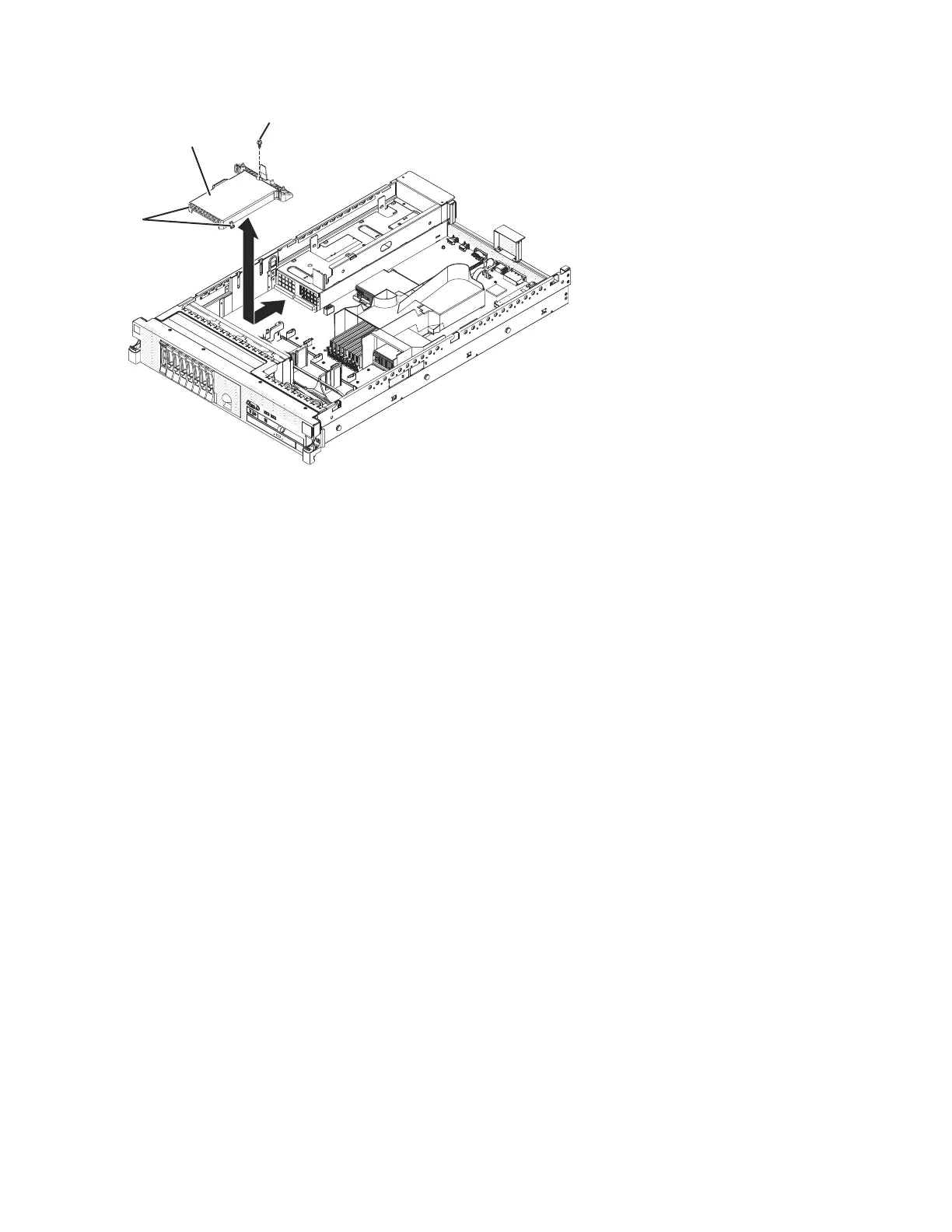
Screw
Safety cover
Alignment
tabs
sonas211
Figure 45. 240 VA safety cover
Chapter 4. File module 155
 Loading...


