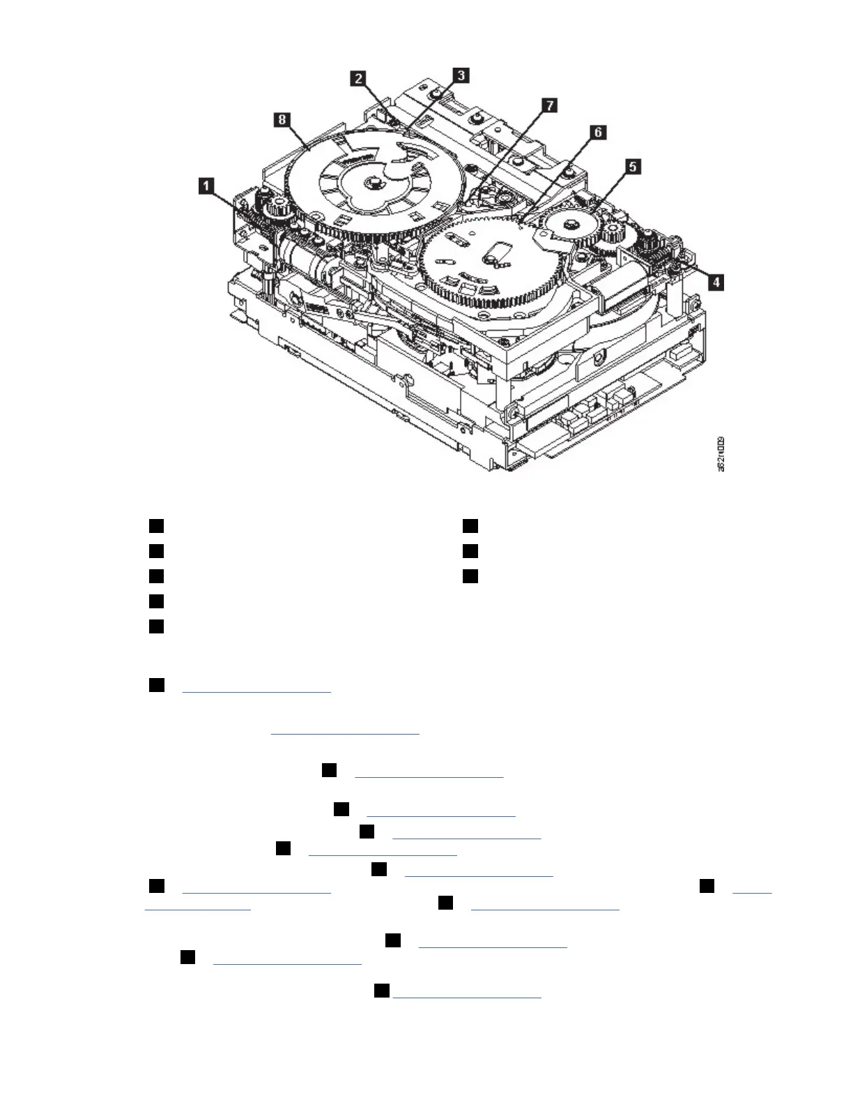
Figure 127. Drive with cover removed to reveal gear train.
1 Loader motor worm gear 6 Threader mechanism gear
2 Cartridge loader tray guide bearing 7 Lever
3 Rotator stub 8 Loader mechanism gear
4 Threader motor worm gear
5 Threader intermediate gear
6. As the tape leader block assembly (LBA) is secured in the cartridge, you hear the LBA retention spring
clips click into place. If you do not hear the click, continue rolling until the threader motor worm gear
(4 in Figure 127 on page 241) stops. The LBA is in the correct position.
Note: Be sure to keep tension on the tape as the LBA is drawn into the cartridge by using a hex
wrench as shown in Figure 126 on page 240.
7. Notice these mechanisms:
a) Loader mechanism gear (6 in Figure 127 on page 241) nearest the front of the drive that actuates
the cartridge loader mechanism.
b) Position of the rotate stub (3 in Fig
ure 127 on page 241
).
c)
Front loader motor worm gear (
1 in Fig
ure 127 on page 241
). Rotating this gear allows the loader
mechanism g
ear (
8 in Fig
ure 127 on page 241
) to turn.
8.
Rotate the loader motor worm gear (
1 in Fig
ure 127 on page 241
) to turn the loader mechanism gear
(6 in Fig
ure 127 on page 241
) counterclockwise. Continue turning until the rotator stub (3 in Fig
ure
127 on page 241) loses contact with the lever (7 in Fig
ure 127 on page 241
). This action releases
the LBA leader pin.
9.
Rotate the threader motor worm gear (
4 in Fig
ure 127 on page 241
) to turn the threader mechanism
g
ear (
6 in Fig
ure 127 on page 241
) counterclockwise. This action moves the LBA out of the cartridge
and pas
t the read/write head. Stop this rotation when the LBA is near the tape guide roller nearest
the rear of the drive that is shown as
1 Fig
ure 128 on page 242
.
IBM Condential
Appendix I. Manual cartridge removal procedure241
 Loading...