2 Wiring
2
- 16 -
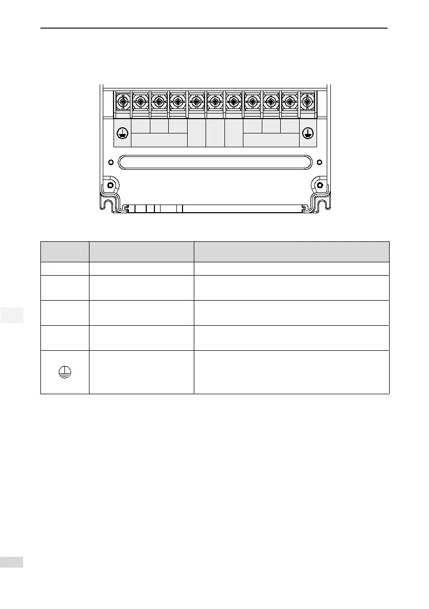
2.3.1 Main Circuit Terminals
Figure 2-6 Terminal block arrangement of IS650P
MOTOR POWER
R S T
BR (+) (-)
U V W
Table 2-1 Names and functions of main circuit terminals
Terminal
Symbol
Terminal Name Terminal Function
R, S, T
Power input terminals Three-phase 380 V power input
BR, (+)
Terminals for connecting
external regenerative resistor
Connect to external regenerative resistor.
(+), (-)
Common DC bus
terminal
They are used for common DC bus connection when
multiple servo drives are used in parallel.
U, V, W
Servo motor connection
terminals
Connect to U, V and W phases of the servo motor.
Ground
Two grounding terminals of the servo drive are respectively
connected to those of the power supply and the servo
motor.
The entire system must be grounded.
 Loading...