− 9 −
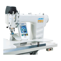
3-9 Connecting the cords
CN38
CN26
CN56
CN57
CN53
CN54
CN55
CN52
CN51
CN25
CN21
CN34
CN62
MAIN circuit
board
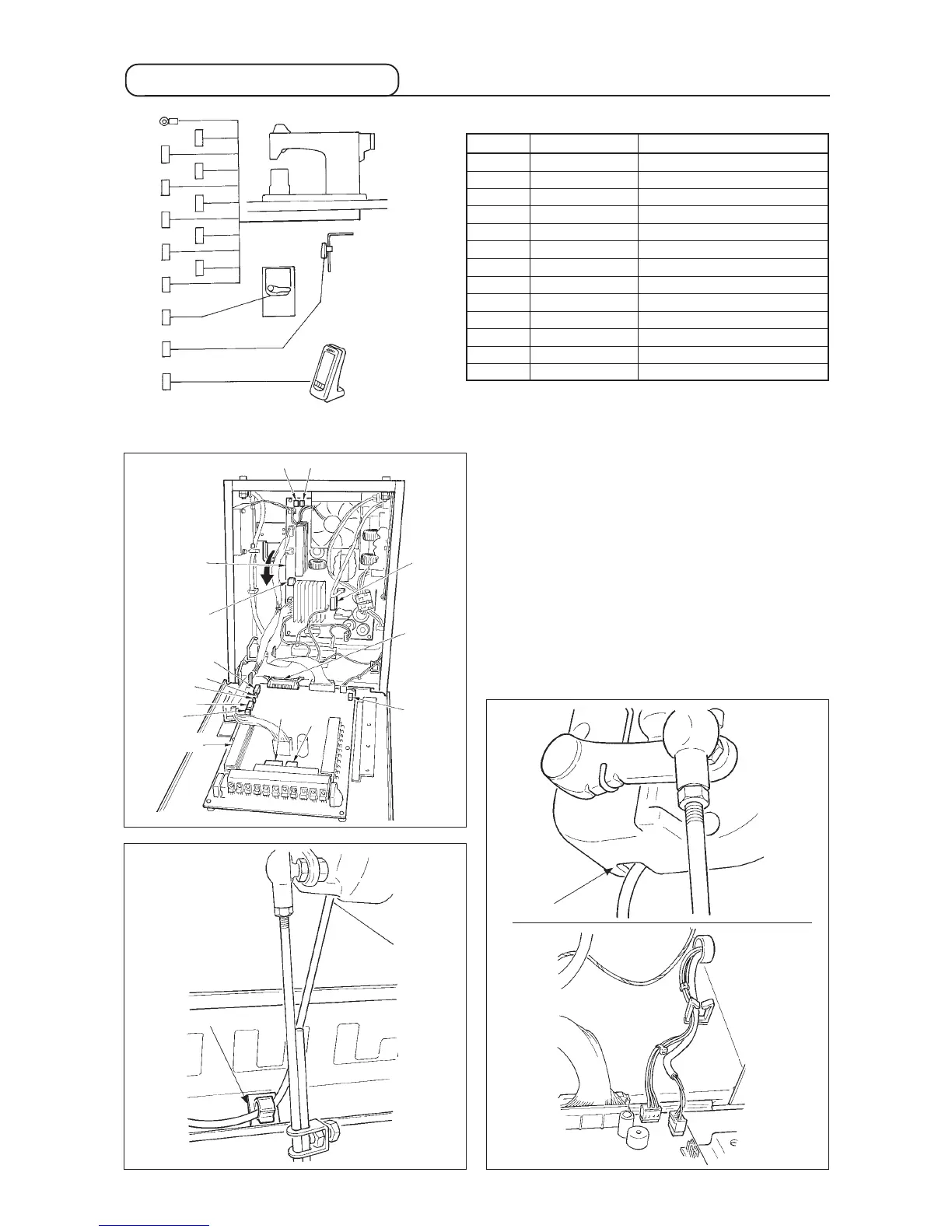
1) Remove the auxiliary pedal cord and insert the
cord into the control box from the cord inserting
port. Pass the auxiliary pedal cord through the rear
side of the auxiliary pedal and insert it into the
control box from hole A located on the lower side
of the pedal sensor.
2) Fix the auxiliary pedal cord with the sticker (small)
so that the cord does not move.
3) Connect CN38, 21, 25, and 26 to PWR p.c.b. CN
25 and 26 can be connected to either one.
Conect others to MAIN p.c.b.
PWR circuit
board
Sticker (small)
A
Cord inserting
port
CN38
CN21
CN25
CN26
CN56
CN57
CN53
CN52
CN51
CN55
CN62
CN54
CN34
Sewing machine head
Auxiliary pedal
Operation panel
Knee SW
Ground wire
Terminal No. of poles Name of cable
CN38 White 4 poles Power cable of main motor
CN21 White 9 poles Encoder cable of main motor
CN25 Red 2 poles Top feed fan cord
CN26 Red 2 poles Bottom feed fan cord
CN56 White 10 poles Feed motor cord
CN57 White 6 poles Auxiliary feed motor cord
CN53 White 6 poles Head relay cord 1
CN52 White 4 poles Head relay cord 2
CN51 White 2 poles Presser lifter cord
CN55 10 poles DATA p.c.b. cord
CN62 Yellow 4 poles
CN54 Red 4 poles
CN34 26 poles
 Loading...